
User manual


AC-tiveMaster Digital
11
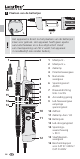
3
2
4
GB
Single-pole phase test
Voltage test
l,@JDBNMS@BSVHSGSGDBNMCTBSNQSNADSDRSDCVHSGSDRSOQNC
L2, L1 remains free during the measurement. The LED (9) will
light up if an AC voltage is applied on the conductor.
l3GDRHMFKDONKDOG@RDSDRSB@MNMKXADODQENQLDCVHSGETKKX
charged batteries inserted.
l3GDRHMFKDONKDOG@RDSDRSB@MADB@QQHDCNTS@REQNL@M "
voltage of approx. 100 V AC.
l6GDMSGDRHMFKDONKDOG@RDSDRSHRB@QQHDCNTSNMSGDNTSDQ
conductor, the indicator function may be adversely affected
under certain conditions (e.g. when insulating personnel
protective equipment is used or at insulated locations).
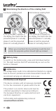
Functional test/Self-test
l3DRSSGDUNKS@FDSDRSDQAX@OOKXHMFHSSNE@LHKH@QUNKS@FD
sources
l"NMMDBSSDRSOQNCR@MC3GD+$#ENQSGDBNMSHMTHSX
test (13) lights up and a signal sounds.
l/QDRRSGD` 43.3$23jATSSNM.MRTBBDRRETKBNLOKDSHNMNE
the test, the LEDs for the continuity test (13) as well as all
segments of the bar graph light up and a signal sounds.
l3GDUNKS@FDSDRSDQHR@TSNL@SHB@KKX@BSHUD@REQNL@UNKS@FDNE
5@MCRGNVRSGDLD@RTQDCUNKS@FDANSGMTLDQHB@KKX
and as a bar graph.
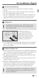
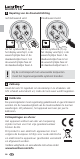
Hold the base device (+)
in your right hand and the
second test prod (-) in your
left hand. Now apply the test
prods to the contacts to be
tested (line, socket, etc.).
The single-pole phase test is not suitable for checking
for zero voltage. To do this, you need to carry out a
two-pole phase test.
!
To achieve the protection class CAT III 1000 V and
" 3(55SGDOQNSDBSHUDBNUDQRLTRSADOK@BDC
over the test prods.
!