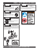
OPERATION AND PARTS MANUAL SERIES MODEL MT-84FA TAMPING RAMMER (ROBIN GASOLINE ENGINE) Revision #0 (06/10/05) To find the latest revision of this publication, visit our website at: www.multiquip.com THIS MANUAL MUST ACCOMPANY THE EQUIPMENT AT ALL TIMES.
MT-84FA — PROPOSITION 65 WARNING PAGE 2 — MT-84FA — OPERATION & PARTS MANUAL — REV.
NOTE PAGE MT-84FA — OPERATION & PARTS MANUAL — REV.
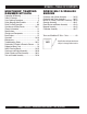
MT-84FA — TABLE OF CONTENTS MULTIQUIP TAMPING RAMMER MT-84FA ROBIN EH-12-2D46420 ENGINE Proposition 65 Warning ......................................... 2 Table Of Contents ................................................. 4 Parts Ordering Procedures ................................... 5 Safety Message Alert Symbols .......................... 6-7 Rules For Safe Operation ..................................8-9 Operation and Safety Decals .........................10-11 General Information ...................
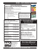
MT-84FA — PARTS ORDERING PROCEDURES When ordering parts, please supply the following information: ❒ ❒ ❒ ❒ ❒ ❒ ❒ Dealer account number Dealer name and address Shipping address (if different than billing address) Return fax number Applicable model number Quantity, part number and description of each part Specify preferred method of shipment: Note: Unless otherwise indicated by customer, all ✓ FedEx or UPS Ground orders are treated as “Standard Orders”, and will ✓ FedEx or UPS Second Day or Third Day ship wit
MT-84FA — SAFETY MESSAGE ALERT SYMBOLS FOR YOUR SAFETY AND THE SAFETY OF OTHERS! HAZARD SYMBOLS Safety precautions should be followed at all times when operating this equipment. Failure to read and understand the Safety Messages and Operating Instructions could result in injury to yourself and others.
MT-84FA — SAFETY MESSAGE ALERT SYMBOLS CAUTION Rotating Parts Hazards NEVER operate equipment with covers, or guards removed. Keep fingers, hands, hair and clothing away from all moving parts to prevent injury. CAUTION CAUTION Equipment Damage Hazards Other important messages are provided throughout this manual to help prevent damage to your light tower, other property, or the surrounding environment.
MT-84FA — RULES FOR SAFE OPERATION DANGER Read this manual! Failure to follow instructions in this manual may lead to serious injury or even death! This equipment is to be operated by trained and qualified personnel only! This equipment is for industrial use only. The following safety guidelines should always be used when operating the MT-84FA Tamping Rammer: GENERAL SAFETY ■ DO NOT operate or service this equipment before reading this entire manual.
MT-84FA — RULES FOR SAFE OPERATION ■ ALWAYS stop the engine before servicing, adding fuel and oil. ■ NEVER run engine without air filter. Severe engine may occur. ■ ALWAYS service air cleaner frequently to prevent carburetor malfunction. ■ ALWAYS check the machine for loosened threads or bolts before starting. ■ ALWAYS be sure the operator is familiar with proper safety precautions and operations techniques before using rammer. ■ ALWAYS store equipment properly when it is not being used.
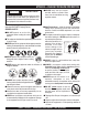
MT-84FA — OPERATION AND SAFETY DECALS Machine Safety Decals The MQ Mikasa tamping rammer is equipped with a number of safety decals. These decals are provided for operator safety and maintenance information. Figure 1 and 1A below and preceeding page illustrates these decals as they appear on the machine. Should any of these decals become unreadable, replacements can be obtained from your dealer. Figure 1. Rammer Operation and Safety Decals PAGE 10 — MT-84FA — OPERATION & PARTS MANUAL — REV.
MT-84FA — OPERATION AND SAFETY DECALS Figure 1A. Rammer Operation and Safety Decals MT-84FA — OPERATION & PARTS MANUAL — REV.
MT-84FA —GENERAL INFORMATION Definition of Tamping Rammer The Mikasa MT-84FA tamping rammer is a powerful compacting tool capable of applying a tremendous force in consecutive impacts to a soil surface. Its applications include soil compacting for road, embankments and reservoirs as well as backfilling for gas pipelines, water pipelines and cable installation work.
MT-84FA — SPECIFICATIONS Table 1. MT-84FA Rammer Specifications MODEL MT-84FA Overall Height 41.5 in. (1055 mm) Overall Width 16.1 in (410 mm) Over Length 28.9 in (735 mm) Shoe Size L x W 13.4 x 11.2 in. (340 x 285 mm) Blows/minute 660-700 Impact Force 3,500 lbs (1,600 kg) Stroke 3.15 in (80 mm) Clutch Automatic Centrifugal Travel Speed 26.2 - 36.1 ft/min (8 - 11 m/min) Lubrication System Oil Bath-10W-30 Motor Oil Fuel Capacity 2.1 q (2.0 liters) Operating Weight (W/Fuel) 203 lbs.
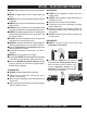
MT-84FA — CONTROLS AND COMPONENTS Figure 2. MT-84FA Rammer Figure 2 shows the location of the controls and components 8. Foot– Laminated wood with tempered steel plate for for the MT-84FA Tamping Rammer. The functions of each superior shock absorption. control is described below: 9. Oil Level Sight Glass – Indicates the level of oil in the oil bath reservoir. 1. Throttle Lever – Controls engine speed and the tamping 10. Recoil Starting Handle – Used when starting the engine. action of the rammer.
MT-84FA — BASIC ENGINE Figure 3. Robin EH-12-2D Engine Controls and Components INITIAL SERVICING The engine (Figure 3) must be checked for proper lubrication and filled with fuel prior to operation. Refer to the manufacturers Engine manual for instructions & details of operation and servicing. 5. Recoil Starter (pull rope) – Manual-starting method. Pull the starter grip until resistance is felt, then pull briskly and smoothly. 1.
MT-84FA — OPERATION This section is intended to assist the operator with the initial start-up of the MT-84FA Tamping Rammer. It extremely important that this section be read carefully before attempting to operate the rammer. Fuel Check 1. Check the fuel level in the fuel tank. If the fuel level is low, fill the fuel tank (Figure 5) with clean unleaded gasoline. DO NOT use your rammer until this section is thoroughly understood.
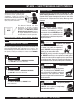
MT-84FA — OPERATION Inspection 1. Check all nuts, bolts fasteners for tightness. Retighten as necessary. 2. Clean any dirt from the recoil starter and foot pedestal. Wipe the entire unit clean before operating. 3. Close the choke lever Figure 9 and move the throttle lever to the "Full Open" position. Turning the choke lever 90 degrees clockwise closes the choke . In cold weather, start the unit with choke fully closed.
MT-84FA — OPERATION Operation 1. To start the rammer tamping action, move the throttle lever (Figure 11) quickly from IDLE (close) to the FULL OPEN position . DO NOT move the throttle lever slowly as this may cause damage to the clutch or spring. 3. To stop the tamping action, move throttle lever quickly from the FULL OPEN to IDLE position. Stopping The Engine Normal Shutdown 1. Move throttle lever quickly from the FULL OPEN to IDLE position (Figure 12) and run the engine for three minutes at low speed.
MT-84FA — MAINTENANCE Maintenance Perform the scheduled maintenance procedures as indicated: DAILY ■ Thoroughly remove dirt and oil from the engine and control area. Clean or replace the air cleaner elements as necessary. Check and retighten all fasteners as necessary. Check the spring box and bellows for oil leaks. Repair or replace as needed.
MT-84FA — TROUBLESHOOTING GUIDE TABLE 4. ENGINE TROUBLESHOOTING SYMPTOM POSSIBLE PROBLEM SOLUTION Difficult to start Fuel is available but spark plug will not ignite. (Power available at high tension cable). Fuel is available but spark plug will not ignite. (Power NOT available at high tension cable). Fuel is available and spark plug ignites (compression normal). Fuel is available and spark plug ignites (compression low ). Ignition plug being bridge? Check ignition system.
MT-84FA — TROUBLESHOOTING GUIDE ENGINE TABLE 4. ENGINE TROUBLESHOOTING (continued) SYMPTOM POSSIBLE PROBLEM SOLUTION Operation not satisfactory Governor adjustment improper? Adjust governor to correct lever. Governor spring defective? Clean or replace ignition. Fuel flow erratic? Check fuel line. Air taken in through suction line? Check suction line. Dust in rotating par t? Clean recoil star ter assembly. Spring spring failure? Replace sprial spring. Rotational speed fluctuates.
MT-84FA — EXPLANATION OF PARTS SECTION REMARKS The following section explains the different symbols and remarks used in the Parts section of this manual. Use the help numbers found on the back page of the manual if there are any questions. The contents and part numbers listed in the parts section are subject to change without notice. Multiquip does not guarantee the availability of the parts listed. Sample Parts List: NO.
MT-84FA — SUGGESTED SPARE PARTS MT-84FA RAMMER 1 TO 3 UNITS MT-84FA RAMMER 3 TO 5 UNITS QTYPART NO QTYPART NO DESCRIPTION 1 .. 362910060 ..... THROTTLE LEVER ASSY 1 .. 956100045 ..... THROTTLE WIRE 5 .. 354030030 ..... ELEMENT, YELLOW 5 .. 354030040 ..... ELEMENT, GRAY 2 .. 354336352 ..... CLAMP, BELLOWS 1 .. 354010010 ..... BELLOWS 1 .. 361910070 ..... CAP, FUEL TANK 1 .. 954300720 ..... COCK, FUEL ASSY. 5 .. 2523260207 ... ELEMENT, SET, ENGINE 1 .. 0660000371 ... STOP SWITCH ASSY 5 .. 0650140580 ...
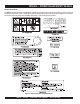
MT-84FA— NAMEPLATE AND DECALS NAME PLATE AND DECALS PAGE 24 — MT-84FA — OPERATION & PARTS MANUAL — REV.
MT-84FA— NAMEPLATE AND DECALS NAME PLATE AND DECALS NO PART NO PART NAME 1 2 3 4 5 8 9 10 11 12 13 14 16 17 18 19 20 21 22 100 101 102 103 920202930 920210150 920106460 920210160 920108310 920203290 DECAL: START SWITCH ................. 1 .......... NPA293 DECAL: 3500 ~ 3700 RPM 1 DECAL: MIKASA 160 MM 1 DECAL: SERVICE MONTHLY .......... 1 .......... NPA1016 DECAL: CLEANER ELEMENT ......... 1 .......... NPA831 DECAL: CAUTION ............................ 1 .......... NPA329 PLATE, SERIAL NO. ............
MT-84FA — CRANKCASE AND ENGINE ASSY. CRANKCASE AND ENGINE ASSY. PAGE 26 — MT-84FA — OPERATION & PARTS MANUAL — REV.
MT-84FA — CRANKCASE AND ENGINE ASSY. CRANKCASE AND ENGINE ASSY. NO. PART NO. PART NAME QTY.
MT-84FA — CRANKCASE AND ENGINE ASSY. CRANKCASE AND ENGINE ASSY. CONTINUED PAGE 28 — MT-84FA — OPERATION & PARTS MANUAL — REV.
MT-84FA — CRANKCASE AND ENGINE ASSY. CRANKCASE AND ENGINE ASSY. CONTINUED NO PART NO PART NAME QTY.
MT-84FA — GUIDE CYLINDER AND FOOT ASSY. GUIDE CYLINDER AND FOOT ASSY. PAGE 30 — MT-84FA — OPERATION & PARTS MANUAL — REV.
MT-84FA — GUIDE CYLINDER AND FOOT ASSY. GUIDE CYLINDER AND FOOT ASSY. NO. PART NO. PART NAME QTY. REMARKS 1 352423290 PISTON PIN 1 2 363457870 PISTON PIN PLUG 2 3 361344360 PISTON ROD 1 4 355452340 PISTON END 1 5 020118150 NUT M18, P1.5 1 6 355447250 STOPPER UPPER 1 7 355447260 STOPPER, LOWER 1 9 355334310 SPRING CYLINDER 1 11 050100900 O-RING G-90 1 12 014210020 SOCKET HEAD BOLT 10X20 T .......... 4 ............REPLACES 001521020 13 014210040 SOCKET HEAD BOLT 10X40 T .......... 4 ............
MT-84FA — TANK AND HANDLE ASSY. TANK AND HANDLE ASSY. PAGE 32 — MT-84FA — OPERATION & PARTS MANUAL — REV.
MT-84FA — TANK AND HANDLE ASSY. TANK AND HANDLE ASSY. NO PART NO PART NAME QTY. REMARKS A 305910032 FUEL TANK ASSY .................................. 1 ............... INCLUDES ITEMS W/ # 1 361118300 HANDLE 1 5 351337070 SHOCK ABSORBER 2 6 009110007 GT CAP SA, 10X20 4 7 012210020 BOLT 10X20 H, SW ................................ 4 ................REPLACES 002211020 9# 362116890 FUEL TANK, GRAY 1 12 011208030 BOLT 8X30 T ........................................... 2 ................
ROBIN EH-12-2D46420 ENGINE — CRANKCASE AND CYLINDER ASSY. CRANKCASE AND CYLINDER ASSY. PAGE 34 — MT-84FA — OPERATION & PARTS MANUAL — REV.
ROBIN EH-12-2D46420 ENGINE — CRANKCASE AND CYLINDER ASSY. CRANKCASE AND CYLINDER ASSY. NO. PART NO. PART NAME QTY. REMARKS 10 2521030131 CRANK CASE ............................ 1 ......................
ROBIN EH-12-2D46420 ENGINE — CRANKSHAFT AND PISTON ASSY. CRANKSHAFT AND PISTON ASSY. MT-84FA — EH12-2D ROBIN ENGINE— CRANKSHAFT AND PISTON PAGE 36 — MT-84FA — OPERATION & PARTS MANUAL — REV.
ROBIN EH-12-2D46420 ENGINE — CRANKSHAFT AND PISTON ASSY. CRANKSHAFT AND PISTON ASSY. NO. PART NO. PART NAME 10 40 40 40 50 60 70 80 105 310 320 * 350 360 360 360 370 370 370 380 2682190111 0230250110 0230250120 0230250130 0021814000 0032014000 0323030010 0053204201 0173120010 2522250110 2362300103 2682330103 2682340103 2682340203 2682340203 2522350117 2522350217 2522350317 2152500403 CRANKSHAFT CP 1 SPACER T=0.6 .......................... 1 ......................
ROBIN EH-12-2D46420 ENGINE—MUFFLER,AIR CLEANER, CAM& CARB. ASSY. MUFFLER,AIR CLEANER,CAMSHAFT & CARBURETOR ASSY. PAGE 38 — MT-84FA — OPERATION & PARTS MANUAL — REV.
ROBIN EH-12-2D46420 ENGINE—MUFFLER,AIR CLEANER, CAM& CARB. ASSY. MUFFLER, AIR CLEANER, CAMSHAFT & CARBURETOR ASSY. NO. PART NO.
ROBIN EH-12-2D46420 ENGINE — GOVERNOR ASSY. GOVERNOR ASSY. PAGE 40 — MT-84FA — OPERATION & PARTS MANUAL — REV.
ROBIN EH-12-2D46420 ENGINE — GOVERNOR ASSY. GOVERNOR ASSY. NO. PART NO. 10 2524230303 20 2264230207 26 0031108000 30 2544270101 40 2544280103 50 0031306000 60 0011406300 70 0186060020 80 2524250323 200 2524340230 210 0116040030 230 0043105250 231 0043104250 235 2684500113 240 0021705000 250 2054600323 280 2264310101 290 2524420213 293 0110060030 710 2524280111 715 0011308160 716 0110060030 PART NAME QTY. REMARKS GOVERNOR LEVER CP 1 GOVERNOR SHAFT .................... 1 ....................
ROBIN EH-12-2D46420 ENGINE — RECOIL STARTER AND BLOWER ASSY. RECOIL STARTER AND BLOWER ASSY. PAGE 42 — MT-84FA — OPERATION & PARTS MANUAL — REV.
ROBIN EH-12-2D46420 ENGINE — RECOIL STARTER AND BLOWER ASSY. RECOIL STARTER AND BLOWER ASSY. NO. 10 20 40 90 95 200 201 * 202 * 203 * 204 * 205 * 206 * 207 * 208 * 211 * 220 249 * PART NO. 2525165221 920100240 0011406550 2685270303 0110060140 2685020130 2705011508 2695012008 2825011118 2615010008 2705012508 2275013108 2275013508 2705026108 2685014518 0110060010 2275015208 PART NAME QTY. REMARKS BLOWER HOUSING CP 2 1 DECAL, M-MARK 1 BOLT & WASHER ASSY 4 HEAD COVER 1 FLANGE BOLT 2 RECOIL STARTER ASSY .....
ROBIN EH-12-2D46420 ENGINE — MAGNETO ASSY. MAGNETO ASSY. PAGE 44 — MT-84FA — OPERATION & PARTS MANUAL — REV.
ROBIN EH-12-2D46420 ENGINE — MAGNETO ASSY. MAGNETO ASSY. NO PART NO 10 2687933201 11 2697943011 30 0011406250 60 0660000371 70 0150040090 75 0566030010 90 0566000250 95 0659000010 100 0650140580 110 2307510113 PART NAME QTY. FLYWHEEL CP 1 IGNITION COIL CP 1 BOLT & WASHER ASSY 2 STOP SWITCH ASSY (ON-OFF) 1 TAPPING SCREW 2 CLAMP 1 CLAMP 1 SPARK PLUG CLIP 1 SPARK PLUG, BR6ES 1 SPARK PLUG CAP 1 REMARKS MT-84FA — OPERATION & PARTS MANUAL — REV.
ROBIN EH-12-2D46420 ENGINE — CARBURETOR ASSY. CARBURETOR ASSY. PAGE 46 — MT-84FA — OPERATION & PARTS MANUAL — REV.
ROBIN EH-12-2D46420 ENGINE — CARBURETOR ASSY. CARBURETOR ASSY.
TERMS AND CONDITIONS OF SALE — PARTS Effective: October 1, 2002 PAYMENT TERMS 5. Parts must be in new and resalable condition, in the original Multiquip package (if any), and with Multiquip part numbers clearly marked. 6. The following items are not returnable: Terms of payment for parts are net 10 days. FREIGHT POLICY All parts orders will be shipped collect or prepaid with the charges added to the invoice. All shipments are F.O.B. point of origin.
NOTE PAGE MT-84FA — OPERATION & PARTS MANUAL — REV.
OPERATION & PARTS MANUAL HERE'S HOW TO GET HELP PLEASE HAVE THE MODEL AND SERIAL NUMBER ON-HAND WHEN CALLING UNITED STATES Multiquip Corporate Office 18910 Wilmington Ave. Tel. (800) 421-1244 Carson, CA 90746 Fax (800) 537-3927 Contact: mq@multiquip.com Mayco Parts 800-306-2926 Fax: 800-672-7877 310-537-3700 Fax: 310-637-3284 Service Department 800-421-1244 Fax: 310-537-4259 310-537-3700 MQ Parts Department 800-427-1244 310-537-3700 MEXICO UNITED KINGDOM MQ Cipsa Carr. Fed. Mexico-Puebla KM 126.