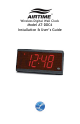
Wireless Digital Wall Clock Model AT-DDC4 Installation & User’s Guide
THIS EQUIPMENT COMPLIES WITH FCC REQUIREMENTS PURSUANT SUBPART J OF PART-15 This device complies with Part 15 of the FCC Rules. Operation is subject to the following two conditions: (1) this device may not cause harmful interference, and (2) this device must accept any interference received, including interference that may cause undesired operation.
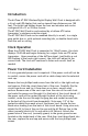
Page 1 Introduction The AirTime AT-DDC Wireless Digital Display Wall Clock is designed with a 4-inch red LED display that can be viewed from distances over 100 feet. The bright red display shows the hour and minutes and can be configured for a 12 or 24 Hour format. The AT-DDC Wall Clock is synchronized by a Lathem ATX series transceiver’s wireless correction signal.
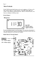
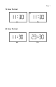
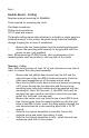
Page 2 Time Formats The AT-DDC4 Series Wall Clocks can be set to display in 12 Hour or 24 Hour format. When in 12 Hour format, a red LED in the upper left corner of the display indicates PM hours. When in 24 Hour format, the hours are displays in Military style. Front Panel To set the display format, use the jumper (J1) located on the back of the circuit board which can be accessed by removing the right side end cap and sliding the circuit board out slightly.
Page 3 12 Hour Format AM PM 24 Hour Format AM PM
Page 4 Mounting The AT-DDC Wall Clock can be mounted directly to a wall, to a single gang outlet box, double hung from the wall or double hung from the ceiling. When deciding where the clock will be mounted, keep in mind that 115VAC power is required. Mounting to a Wall Tools required for mounting the clock: Drill with a 5/16" bit Hammer Phillips head screwdriver Wall anchors Pencil After deciding the location where the clock will be mounted, make two marks 12" apart and horizontal.
Page 5 Mounting to a Single Gang Box Two mounting holes have been located in the center of the case 2 1/4" apart for mounting to a single gang wall box. A 7/8" hole has been placed between the mounting holes that will accept conduit if desired. Note: If mounting near a ceiling, make sure the top of the single gang box is at least 2 1/4" away from the ceiling. Note: Make sure you have at least 16" of side clearance on one side in order to remove the front panel.
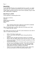
Page 6 Double Mount – Wall The AT-DDC requires optional mounting kit (SAM0625) Tools required for mounting the clock: Flat blade screwdriver Phillips head screwdriver 15/16" open end wrench The double wall mount plate attaches to a double or single gang box installed securely in the wall. Required wiring should be available through the gang box at time of installation. Remove the two chase nipples from the mounting plate posts. Secure the mounting plate securely to the gang box with the proper screws.
Page 7 » » » » Line the two posts from the mounting plate up with the two holes of the modified end cap. Insert the chase nipples through the holes of the modified end cap and secure to the mounting plate with a 15/16" wrench. Slide the front panel assemblies in partially. Secure the required wiring and install the battery if used. Slide the front panel assemblies in fully. Install the end caps and secure each with its two screws. Discard or store the two original end caps the modified end caps replaced.
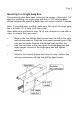
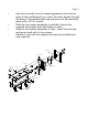
Page 8 Double Mount - Ceiling Requires optional mounting kit (SAM0626) Tools required for mounting the clock: Flat blade screwdriver Phillips head screwdriver 15/16" open end wrench The double ceiling mount plate attaches to a double or single gang box installed securely in the ceiling. Required wiring should be available through the gang box at time of installation. Remove the two chase nipples from the mounting plate posts. Secure the mounting plate securely to the gang box with the proper screws.
Page 9 mounting plate #10 hex nuts D DC4 cases chase nipple chase nipple #10 lock washers #10 screws
Page 10 Specifications Dimensions Weight 6 3/4" H X 15 1/2" W X 3 1/8" D 17.1 cm H X 39 cm W X 7.9 cm D 9 lbs. (4.086 kg) Display 3 3/4-Inch Red 4 Segment LED Housing Extruded aluminum main case with black textured paint, molded plastic end caps with black texture.
Page 11 One Year Limited Warranty Lathem warrants the hardware products described in this guide against defects in material and workmanship for a period of one year from date of original purchase from Lathem or from an authorized Lathem reseller. The conditions of this warranty and the extent of the responsibility of Lathem Time Corporation (“Lathem”) under this warranty are listed below. 1.