Wireless Digital Wall Clock Model ATDDC4 Installation & User’s Guide
THIS EQUIPMENT COMPLIES WITH FCC REQUIREMENTS PURSUANT SUBPART J OF PART-15 Other AirTime Products This device complies with Part 15 of the FCC Rules. Operation is subject to the following two conditions: (1) this device may not cause harmful interference, and (2) this device must accept any interference received, including interference that may cause undesired operation.
ATDDC4 Series Installation & User’s Guide ATDDC4 Series Installation & User’s Guide One Year Limited Warranty Lathem warrants the hardware products described in this guide against defects in material and workmanship for a period of one year from date of original purchase from Lathem or from an authorized Lathem reseller. The conditions of this warranty and the extent of the responsibility of Lathem Time Corporation (“Lathem”) under this warranty are listed below. 1.
ATDDC4 Series Installation & User’s Guide Specifications Clock Installation Tools required for mounting the clock: • • • • • ATDDC4 Series Installation & User’s Guide Drill with a 5/16" bit Hammer Phillips head screwdriver Wall anchors Pencil Separate the electronics from the enclosure and to set the Time Display Format (12hr / 24hr). To do this, remove the plastic end caps, each secured with two Phillips-head screws.
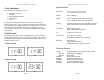
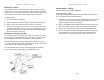
ATDDC4 Series Installation & User’s Guide ATDDC4 Series Installation & User’s Guide To set the display format, use the jumper (J1) located on the back of the circuit board which can be accessed by removing the right side end cap and sliding the circuit board out slightly. Back Side of Circuit Board Jumper J1 On = 12 Hour display Off = 24 Hour display Mounting the Enclosure 5. Slide the circuit board assemblies in partially and secure the required wiring. 6.
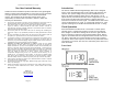
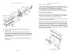
ATDDC4 Series Installation & User’s Guide Mounting to a Wall After deciding where to mount the clock, make two marks 12" apart and horizontal. Note: If mounting near a ceiling, make sure the holes are at least 2 1/4" away from the ceiling. Also, provide at least 16" of side clearance on one side in order to remove the front panel. Installation Steps 1. Drill a 5/16" hole at each mark 2. Insert a wall anchor and tap it flush to the wall with the hammer. 3.
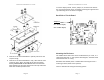
ATDDC4 Series Installation & User’s Guide ATDDC4 Series Installation & User’s Guide Power Connection – Wall Mount 120vAC Electrical Supply can be brought into the ATDDC4 enclosure from any of the six vent-hole positions, from the back, or from either side. Conduit access is not available from the bottom. Note: Optional plastic end-panels may be ordered (left VIS1551-L), (right VIS1551-R) that have access holes pre-drilled for side access .
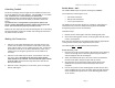
ATDDC4 Series Installation & User’s Guide ATDDC4 Series Installation & User’s Guide Double Mount – Wall Attaching Conduit The ATDDC4 SERIES requires optional mounting kit (SAM0625) The Electrical Supply can be brought into the ATDDC4 enclosure from any of the top three vent-hole positions, from the back, or from either side. Conduit access is not available from the bottom.