Digital Display Wall Clock DDC2 / DDC4 Series Installation & User's Guide
OMNI:CHRON, mini:master, Lathem and the Lathem logo are registered trademarks of Lathem Time Corporation. Other product names mentioned in this manual may be trademarks of their respective companies and are hereby acknowledged. WARNING: Changes or modifications to this product not expressly approved by the party responsible for compliance could void the user’s authority to operate this equipment. This device complies with Part 15 of the FCC Rules.
Table of Contents Introduction..................................................................................................................................................... 1 Clock Operation.............................................................................................................................................. 1 About this Manual ..........................................................................................................................................
DDC4 (Double Mount - Ceiling) .......................................................................................................... 19 Setting the Time............................................................................................................................................ 20 Time Formats............................................................................................................................................ 20 12 Hour Format..........................................
As a Count Up Timer ............................................................................................................................ 52 As a Count Down Timer ....................................................................................................................... 52 Appendix E - LTR-GPS Satellite Receiver / Clock Synchronizer ................................................................ 53 Connecting to a Lathem DDC2-RS or DDC4-RS Digital Clock ..................................
Page 1 Digital Display Wall Clock Guide Introduction The Digital Display Series Wall Clocks are designed with 2-inch or 4-inch red LED displays that can be viewed from great distances; the 4-inch model as far away as 100 feet, the 2-inch model from as far away as 50 feet. The bright red display shows the hour and minutes and can be configured for a 12 or 24 hour format.
Digital Display Wall Clock Guide Page 2 About this Manual This manual will guide you through the installation, setup and wiring of your DDC Series Wall Clock. This manual covers the four available DDC Series models.
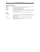
Page 3 Digital Display Wall Clock Guide Optional Accessories VSE0050 SAM0626 SAM0630 SAM0625 VSE0052 DDC-TC LTR4-512 LTR8-512 LTR8-512M Mlink SWIFT-485 plus Power Cord, 6 feet. DDC Series Wall Clocks are shipped without power cords. Double Ceiling Mount Kit for DDC2 or DDC4 Series Double Wall Mount Kit for DDC2 Series Double Wall Mount Kit for DDC4 Series Mounting Bracket for 3510 Hz Electronic Receiver.
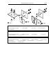
Digital Display Wall Clock Guide Page 4 SAM0626 Kit (left) Includes: 1 - Mounting Plate Assembly 8 - #10 Hex Nuts 2 - Chase Nipples 4 - #10 Screws 8 - #10 Lock Washers SAM0630 Kit (middle) Includes: 1 - Mounting Plate Assembly 2 - Modified End Caps 8 - #10 Lock Washers 4 - #10 Hex Nuts 2 - Chase Nipples 4 - #10 Screws SAM0625 Kit (right) Includes: 1 - Mounting Plate Assembly 2 - Modified End Caps 1 - End Cap Support 2 - Chase Nipples 4 - #10 Screws 8 - #10 Lock Washers 4 - #10 Hex Nuts 4 - #6 Screw
Page 5 Digital Display Wall Clock Guide Configuring the DDC Series Wall Clock Setting the DIP Switches - DDC2 / DDC4 Series DDC2 Remove the four phillips head screws from the left or the right end cap and remove. Slide the lens and circuit board assembly out of the case. Place the lens aside and carefully flip the circuit board assembly over and lay it face down on a clean, smooth work surface.
Digital Display Wall Clock Guide Page 6 DIP Switch Settings Table 1 - S1 (1-5) Secondary Clock Correction 1 2 3 4 5 Secondary Clock Selection 0=Closed 0 1 0 1 0 1 0 1 0 1 0 1 0 1 0 1 0 1 0 1 0 1 0 0 1 1 0 0 1 1 0 0 1 1 0 0 1 0 1 1 0 0 1 1 0 0 0 0 1 1 1 1 0 0 0 0 1 1 1 0 0 0 1 1 1 1 0 0 0 0 0 0 0 0 1 1 1 1 1 1 1 0 0 0 0 0 0 0 0 0 0 0 0 0 0 0 0 0 0 0 0 0 0 1 1 1 1 1 1 1 1=Open *=Factory Default Stand Alone * 3-Wire Synchronous 3-Wire Minute Impulse (59th Minute) 3-Wire Minute Impulse (59th Minu
Page 7 Digital Display Wall Clock Guide Configuring RS485 Communications - DDC2/4-RS Series When multiple DDC2 (4)-RS Series Wall Clocks are installed as slave units to either the Lathem LTR4512 or LTR8-512 Master, LTR0 Mini-Master, Terminal Manager Software or the OMNI:CHRON Time Clock, the last clock on the line must have a shunt installed over both pins at position J2 (see figure 2, page 9). When shipped, the shunt is placed over only one pin of position J2 in an "open" setting.
Digital Display Wall Clock Guide Page 8 When used as a RS485 clock, the master clock will send a signal to the wall clock every minute. The 9Volt alkaline battery (not included) is optional in these types of installations. Battery Installation - DDC2 / DDC4 Series DDC2 Remove the four phillips head screws from the left or the right end cap and remove. Slide the lens and circuit board assembly out of the case.
Page 9 Digital Display Wall Clock Guide AC Return) Attach the ground wire of the cord (normally green) to the green ground screw located on the inside back of the case. Slide the lens and circuit board assembly back into the case, replace the end cap and secure with the four phillips head screws. DDC4-RS Remove the two phillips head screws from the left or the right end cap and remove. Slide the front panel assembly out of the case.
Digital Display Wall Clock Guide Page 10 Replacing an Existing DDC4 Wall Clock When replacing an older style DDC4 Wall Clock it will be necessary to remove any connectors used by the older style clock and attach the wires to the new DDC Series Wall Clock as described above. Board Layout Diagram Fly Lead Connector Jumper J2 J1 Hours Minutes Up Down Ground Beeper DD+ 1 2 3 4 5 6 7 Lathem Time Corp.
Page 11 Digital Display Wall Clock Guide Mounting - DDC2 / DDC4 Series The DDC Series Wall Clocks can be mounted directly to a wall, to a single gang outlet box, double hung from the wall or double hung from the ceiling. When deciding where the clock will be mounted, keep in mind that 115VAC power may be required depending on the installation type. See page 14, figure 3.
Digital Display Wall Clock Guide » Page 12 Slide the lens and circuit board assembly back into the case, replace the end cap and secure with the four phillips head screws. DDC4 » After deciding the location where the clock will be mounted, make two marks 12" apart and horizontal. Note: If mounting near a ceiling, make sure the holes are at least 2 1/4" away from the ceiling. Note: Make sure you have at least 16" of side clearance on one side in order to remove the front panel.
Page 13 Digital Display Wall Clock Guide DDC2 Note: If mounting near a ceiling, make sure the top of the single gang box is at least 2 1/4" away from the ceiling. Note: Make sure you have at least 10 1/2" of side clearance on one side in order to remove the lens and circuit board assembly. » » » » » Remove the four phillips head screws from the left or the right end cap and remove. Slide the lens and circuit board assembly out of the case and set aside.
Digital Display Wall Clock Guide » Page 14 Slide the front panel display back into the case, replace the end cap and secure with the two phillips head screws.
Page 15 Digital Display Wall Clock Guide Note: The long dimension of the mounting plate must be perpendicular to the ground to assure proper alignment of wall clocks. See page 15, figure 4 for DDC2 details. See page 16, figure 5 for DDC4 details. DDC2 (Double Mount - Wall) » » » » » » » » Remove the four phillips head screws from the left and the right end caps of the two DDC2 clocks and remove. Slide the lenses and circuit board assemblies out of the cases and set aside.
Digital Display Wall Clock Guide Page 16 DDC4 (Double Mount - Wall) » » » » » » » » Remove the two phillips head screws from the left and the right end caps of the two DDC4 clocks and remove. Slide the front panel assemblies out of the cases and set aside. Place the two DDC4 clocks back to back and secure by inserting a #10 screw through the two key holes and the two lower mounting holes using lock washers and nuts supplied with the mounting kit.
Page 17 Digital Display Wall Clock Guide Double Mount - Ceiling Requires optional mounting kit (SAM0626) Tools required for mounting the clock: Flat blade screwdriver Phillips head screwdriver 15/16" open end wrench The double ceiling mount plate attaches to a double or single gang box installed securely in the ceiling. Required wiring should be available through the gang box at time of installation. » » Remove the two chase nipples from the mounting plate posts.
Digital Display Wall Clock Guide Page 18 DDC2 (Double Mount - Ceiling) Note: Make sure you have at least 10 1/2" of side clearance on one side in order to remove the lens and circuit board assembly. » » » » » » Remove the four phillips head screws from the left and the right end caps of the two DDC2 clocks and remove. Slide the lenses and circuit board assemblies out of the cases and set aside.
Page 19 Digital Display Wall Clock Guide DDC4 (Double Mount - Ceiling) Note: Make sure you have at least 16" of side clearance on one side in order to remove the front panel assembly. » » » » » » Remove the two phillips head screws from the left and the right end caps of the two DDC4 clocks and remove. Slide the front panel assemblies out of the cases and set aside.
Digital Display Wall Clock Guide Page 20 Setting the Time Time is set on the DDC Series Wall Clocks by depressing buttons located on the left side of the front panel. There are two setting buttons, "H" for hour and "M' for minute. » To advance the hour or minute to the correct time one digit at a time press and release the proper button. Do this as many times as required until the correct time is displayed.
Page 21 Digital Display Wall Clock Guide DDC2 / 4-RS Wiring Appendix A - DDC2-RS / 4-RS Secondary Clock Wiring Diagrams Note: See Appendix B for DDC2-RS-24 / DDC4-RS-24 wiring. Stand-Alone (115VAC) H M BLK GRND AC IN AC RTN BLK 115VAC Local Power Hour and Minutes must be set manually. Use of a 9Volt alkaline battery is recommended to avoid resets after power failures. Set switches 1-5 of S1 as shown.
DDC2 / 4-RS Wiring Digital Display Wall Clock Guide Page 22 3-Wire Synchronous (115VAC) H M BLU / WHT BRN / WHT BLK BLK 115VAC From Master Clock Run AC Return Correction Clock will correct minutes hourly at HH:59 and hour and minutes twice daily at 5:59. Wiring applies to secondary wall clocks such as: Lathem type SS Cincinnati D10 IBM 77 Series To Other Clocks Set switches 1-5 of S1 as shown.
Page 23 Digital Display Wall Clock Guide DDC2 / 4-RS Wiring 3-Wire Synchronous (24VAC) H M BLU / WHT BRN / WHT GRND AC IN AC RTN BLK 24VAC From Master Clock BLK 115VAC Local Power Return To Other Clocks Correction Clock will correct minutes hourly at HH:59 and hour and minutes twice daily at 5:59. Wiring applies to secondary wall clocks such as: Lathem type SS Cincinnati D10 IBM 77 Series Set switches 1-5 of S1 as shown.
DDC2 / 4-RS Wiring Digital Display Wall Clock Guide Page 24 3-Wire minute Impulse (59th Minute) H M BRN / WHT VIO / WHT YEL / WHT BLK 24VDC From Master Clock GRND AC IN AC RTN BLK 115VAC Local Power A B C To Other Clocks Clock must be set within 20 minutes of actual time for master to synchronize. Use of a 9Volt alkaline battery is recommended to avoid resets after power failures.
Page 25 Digital Display Wall Clock Guide DDC2 / 4-RS Wiring 3-Wire Minute Impulse (59th Minute With 12 Hour Correction) H M BRN / WHT VIO / WHT YEL / WHT BLK 24VDC From Master Clock GRND AC IN AC RTN BLK 115VAC Local Power A B C To Other Clocks Clock will correct minutes hourly at HH:58 and hour and minutes twice daily at 5:58. Set switches 1-5 of S1 as shown.
DDC2 / 4-RS Wiring Digital Display Wall Clock Guide Page 26 Standard Electric Synchronous H M BLU / WHT BRN / WHT BLK BLK 115VAC From Master Clock Run AC Return Correction Clock will correct minutes hourly at HH:59 and hour and minutes twice daily at 5:12. For 24VAC applications, use wiring shown on page 18 To Other Clocks Set switches 1-5 of S1 as shown.
Page 27 Digital Display Wall Clock Guide DDC2 / 4-RS Wiring Standard Electric AR-2A 2-Wire Dual Voltage H M BRN / WHT YEL / WHT BLK 24VDC / 48VDC From Master Clock GRND AC IN AC RTN BLK 115VAC Local Power AB To Other Clocks PC Clock must be set to actual time. Use of a 9Volt alkaline battery is recommended to avoid resets after power failures. Set switches 1-5 of S1 as shown.
DDC2 / 4-RS Wiring Digital Display Wall Clock Guide Page 28 Standard Electric AR-2 2-Wire Dual Voltage H M BRN / WHT YEL / WHT BLK 24VDC / 48VDC From Master Clock GRND AC IN AC RTN BLK 115VAC Local Power AB To Other Clocks PC Set switches 1-5 of S1 as shown. Clock must be set to actual time. Use of a 9Volt alkaline battery is recommended to avoid resets after power failures.
Page 29 Digital Display Wall Clock Guide DDC2 / 4-RS Wiring Synchronous Wired H M BLU / WHT BRN / WHT Run AC Return Correction Clock will correct minutes hourly at HH:58 and hour and minutes twice daily beginning at 5:05. For 24VAC applications, use wiring shown on page 18 Faraday To Other Clocks Set switches 1-5 of S1 as shown.
DDC2 / 4-RS Wiring Digital Display Wall Clock Guide Page 30 Simplex 59th Minute Dual Motor H M BLU / WHT BRN / WHT BLK BLK 115VAC From Master Clock Run AC Return Correction Clock must be set to proper hour. Clock will correct minutes hourly at HH:58. . Use of a 9Volt alkaline battery is recommended to avoid resets To Other Clocks Set switches 1-5 of S1 as shown.
Page 31 Digital Display Wall Clock Guide DDC2 / 4-RS Wiring Simplex 45th Minute Dual Motor H M BLU / WHT BRN / WHT BLK BLK 115VAC From Master Clock Run AC Return Correction Clock must be set to proper hour. Clock will correct minutes hourly at HH:45. . Use of a 9Volt alkaline battery is recommended to avoid resets For 24VAC applications, use wiring shown on page 18 To Other Clocks Set switches 1-5 of S1 as shown.
DDC2 / 4-RS Wiring Digital Display Wall Clock Guide Page 32 Edwards Dual Motor H M BLU / WHT BRN / WHT BLK BLK 115VAC From Master Clock Run AC Return Correction Clock must be set to actual time. Use of a 9Volt alkaline battery is recommended to avoid resets after power failures. For 24VAC applications, use wiring shown on page 18 To Other Clocks Set switches 1-5 of S1 as shown.
Page 33 Digital Display Wall Clock Guide DDC2 / 4-RS Wiring Standard Electric AR-3 3-Wire Minute Impulse H M BRN/ WHT VIO / WHT YEL / WHT BLK 24VDC / 48VDC From Master Clock GRND AC IN AC RTN BLK 115VAC Local Power 24 VDC Pulse 48 VDC Correction Common Clock must be set to actual time. Use of a 9Volt alkaline battery is recommended to avoid resets after power failures. To Other Clocks Set switches 1-5 of S1 as shown.
DDC2 / 4-RS Wiring Digital Display Wall Clock Guide Page 34 National Synchronous Wired H M BLU / WHT BRN / WHT BLK BLK 115VAC From Master Clock Run AC Return Correction Clock will correct minutes hourly at HH:00 and hour and minutes twice daily at 6:00. To Other Clocks Set switches 1-5 of S1 as shown.
Page 35 Digital Display Wall Clock Guide DDC2 / 4-RS Wiring Stromberg Synchronous Wired (56th Minute) H M BLU / WHT BRN / WHT BLK BLK 115VAC From Master Clock Run AC Return Correction Clock will correct minutes hourly at HH:56 and hour and minutes twice daily at 11:56. To Other Clocks Set switches 1-5 of S1 as shown.
DDC2 / 4-RS Wiring Digital Display Wall Clock Guide Page 36 Cincinnati D1 H M BRN / WHT YEL / WHT BLK 24VDC / 60VDC From Master Clock GRND AC IN AC RTN BLK 115VAC Local Power A To Other Clocks COMMON Clock must be set within 20 minutes of actual time for master to synchronize. Use of a 9Volt alkaline battery is recommended to avoid resets after power failures. Set switches 1-5 of S1 as shown.
Page 37 Digital Display Wall Clock Guide DDC2 / 4-RS Wiring Cincinnati D6, Edwards 2406 H M YEL / WHT VIO / WHT BLK 24-36VDC From Master Clock GRND AC IN AC RTN BLK 115VAC Local Power AB To Other Clocks PC Clock must be set within 20 minutes of actual time for master to synchronize. Use of a 9Volt alkaline battery is recommended to avoid resets after power failures. Set Setswitches switches1-5 1-5ofofS1SW1 as shown. as shown.
DDC2 / 4-RS Wiring Digital Display Wall Clock Guide Page 38 2-Wire Pulse Alternating (24VDC) H M YEL / WHT VIO / WHT BLK 24VDC From Master Clock GRND AC IN AC RTN BLK 115VAC Local Power A To Other Clocks B Clock must be set within 20 minutes of actual time for master to synchronize. Use of a 9Volt alkaline battery is recommended to avoid resets after power failures. Set switches 1-5 of S1 as shown.
Page 39 Digital Display Wall Clock Guide DDC2 / 4-RS Wiring Electronic Coded H M BRN / WHT BLU / WHT BLK GRND AC IN AC RTN BLK 115VAC Local Power GRAY 3510 Hz RED Reciever WHT Requires 3510Hz receiver (not supplied) Set switches 1-5 of S1 as shown. Clock will correct minutes hourly at HH:57 and hour and minutes twice daily at 5:57.
DDC2 / 4-RS Wiring Digital Display Wall Clock Guide Page 40 Straight Frequency H M BRN / WHT BLU / WHT BLK GRND AC IN AC RTN BLK 115VAC Local Power GRAY 3510 Hz RED Reciever WHT Requires 3510Hz receiver (not supplied) Set switches 1-5 of S1 as shown. Clock will correct minutes hourly at HH:57 and hour and minutes twice daily at 5:57.
Page 41 Digital Display Wall Clock Guide DDC2 / 4-RS Wiring 3-Wire Minute Impulse (58th Minute) H M BRN / WHT VIO / WHT YEL / WHT BLK 24VDC From Master Clock GRND AC IN AC RTN BLK 115VAC Local Power A B C Clock must be set within 20 minutes of actual time for master to synchronize. Use of a 9Volt alkaline battery is recommended to avoid resets after power failures. To Other Clocks Set switches 1-5 of S1 as shown.
DDC2 / 4-RS Wiring Digital Display Wall Clock Guide Page 42 3-Wire Minute Impulse (44th Minute) H M BRN / WHT VIO / WHT YEL / WHT BLK 24VDC From Master Clock GRND AC IN AC RTN BLK 115VAC Local Power A B C Clock must be set within 20 minutes of actual time for master to synchronize. Use of a 9Volt alkaline battery is recommended to avoid resets after power failures. To Other Clocks Set switches 1-5 of S1 as shown.
Page 43 Digital Display Wall Clock Guide DDC2 / 4-RS Wiring 2-Wire Reverse Polarity Minute Impulse (59th Minute) H M YEL / WHT VIO / WHT BLK 24VDC From Master Clock GRND AC IN AC RTN BLK 115VAC Local Power AB To Other Clocks PC Clock must be set within 20 minutes of actual time for master to synchronize. Use of a 9Volt alkaline battery is recommended to avoid resets after power failures. Set switches 1-5 of S1 as shown.
DDC2 / 4-RS -24 Wiring Digital Display Wall Clock Guide Page 44 Appendix B - DDC2-RS-24 / DDC4-RS-24 Wiring The DDC2-RS-24 and the DDC4-RS-24 allow for 24VAC supplied from the Master Clock or Power Supply to power it for normal operation. These models can be used in installations where local 115VAC power may not be available. When shipped, the DDC2-RS-24 and DDC4-RS-24 have an optional power transformer that allows for 24VAC operation.
Page 45 Digital Display Wall Clock Guide DDC2 / 4-RS -24 Wiring DDC2-RS-24 / DDC4-RS-24 Wiring H M BLU / WHT BRN / WHT BLK BLK 24VAC From Master Clock Run AC Return Correction To Other Clocks Set switches 1-5 of S1 as shown.
DDC2 / 4-RS -485 Wiring Digital Display Wall Clock Guide Page 46 Appendix C - RS485 Wiring Diagrams RS485 Data Format The data string that sends the time to the DDC2 / DDC4 Series Wall Clocks is formatted in such a manner that a utility can be written to achieve time updates from a personal computer. The following table shows the layout and explains each character. Data Format 0#112233445566777Z,CR The data string is compiled of a total of 16 characters. These characters represent the following.
Page 47 Digital Display Wall Clock Guide DDC2 / 4-RS -485 Wiring OMCII to DDC2-RS / 4-RS 115VAC Local Power BLK BLK H M GND Trans + Trans - To Other Clocks OMCII DB9 Female Plug Pin 1 2 8 Signal Transmit Data (-) Transmit Data (+) Signal Ground D- of JP4 OMC II D+ of JP4 GND of JP4 11 : 30 DDC2-RS / 4-RS - JP4 Connector Signal Transmit Data (-) Transmit Data (+) Signal Ground Cable should be RS232 twisted pair / CAT3 or CAT5 type. Maximum distance to last DDC Clock is 4000 feet.
DDC2 / 4-RS -485 Wiring Digital Display Wall Clock Guide Page 48 LTR0 to DDC2-RS / 4-RS 115VAC Local Power BLK BLK H M D- of JP4 D+ of JP4 GND of JP4 LTR 0 BLK ORN GRY To Other Clocks LTR0 Fly Leads Wire Gray Orange Black Signal Transmit Data (-) Transmit Data (+) Signal Ground DDC2-RS / 4-RS - JP4 Connector Signal Transmit Data (-) Transmit Data (+) Signal Ground Cable should be RS232 twisted pair / CAT3 or CAT5 type. Maximum distance to last DDC Clock is 4000 feet.
Page 49 Digital Display Wall Clock Guide DDC2 / 4-RS -485 Wiring LTR4 / 8-512 to DDC2-RS / 4-RS 115VAC Local Power BLK BLK H M LTR4 / 8-512 D- of JP4 D+ of JP4 11 : 30 D+ D- To Other Clocks LTR4 / 8-512 Terminal Connections Terminal # 9 (D-) 8 (D+) Signal Transmit Data (-) Transmit Data (+) DDC2-RS / 4-RS - JP4 Connector Signal Transmit Data (-) Transmit Data (+) Cable should be RS232 twisted pair / CAT3 or CAT5 type. Maximum distance to last DDC Clock is 4000 feet.
DDC-TC Timer Control Panel Digital Display Wall Clock Guide Page 50 Appendix D - DDC-TC Timer Control Panel Wiring The DDC-TC can be connected to the DDC Series Wall Clock with a 6 conductor CAT3 or CAT5 network cable. The DDC-TC can be mounted up to 200 feet from the DDC Series Wall Clock. The DDC-TC comes with 6 wire nuts to connect the network cable to the 6 control wires mounted on the back of the DDC-TC. The 6 control wires include Up, Down, Hours, Minutes, Beeper and Ground.
Page 51 Digital Display Wall Clock Guide DDC-TC Timer Control Panel Installation The DDC-TC mounts directly to a standard, double-gang wall box. (not included) Once the wiring has been attached, place the wires inside the double-gang wall box and mount the DDC-TC to the box with the four screws supplied with the DDC-TC by inserting them through the mounting holes and securing.
DDC-TC Timer Control Panel Digital Display Wall Clock Guide Page 52 Operation As a Count Up Timer To start the count: To pause the count: To continue the count: To return to clock mode: press Count Up press Stop / Continue press Stop / Continue press Quit As a Count Down Timer To set hours: To set minutes: To start the count: To pause the count: To continue the count: To return to clock mode: press Set Hours (defualt is 00: ) press Set Minutes (defualt is :00) press Count Down press Stop / Continue pr
Page 53 Digital Display Wall Clock Guide Specifications Appendix E - LTR-GPS Satellite Receiver / Clock Synchronizer Lathem’s LTR-GPS is a Global Positioning Satellite receiver using 12-channels to access the accurate date and time signal transmitted each second by 24 satellites in geosynchronous orbit around the globe. The package includes an amplified GPS Antenna, which must be mounted out-doors or beneath a roof skylight, facing skyward.
Warranty Digital Display Wall Clock Guide The LTR-GPS package includes: LTR-GPS Satellite Synchronizer 115vAC, 2.7w, 50/60Hz Power Adapter Active GPS Antenna with 25ft. Cable Antenna Mounting Bracket and Hardware Installation and Set-Up Guide Separately, from Lathem, for Installer convenience: GPS-INSTALL-TOOLS: Battery / Beeper assemblies aid in Antenna positioning LTR-GPS Specifications: Size / Weight 3.25”x 2”x6.6” / 1 lb.
Page 55 Digital Display Wall Clock Guide Connecting to a Lathem DDC2-RS or DDC4-RS Digital Clock DDC2-RS / DDC4-RS Specifications
Warranty Digital Display Wall Clock Guide Page 56 Appendix F - Specifications Dimensions DDC2 DDC4 4 7/8" H X 10 1/4" W X 3 1/8" D 12.4 cm H X 26.2 cm W X 7.9 cm D 6 3/4" H X 15 1/2" W X 3 1/8" D 17.1 cm H X 39 cm W X 7.9 cm D Weight DDC2 DDC4 3.2 lbs (1.451 kg) 9 lbs. (4.086 kg) Display DDC2 DDC4 1 3/4-Inch Red 7 Segment LED 3 3/4-Inch Red 7 Segment LED Housing DDC2 Extruded aluminum main case with black textured paint, red lexan panel; steel end caps with black textured paint.
Page 57 Digital Display Wall Clock Guide Specifications Appendix G - Warranty Limited One-Year Limited Warranty Lathem warrants the hardware products described in this guide against defects in material and workmanship for a period of one year from date of original purchase from Lathem or from an authorized Lathem reseller. The conditions of this warranty and the extent of the responsibility of Lathem Time Corporation (“Lathem”) under this warranty are listed below. 1. 2. 3. 4. 5. 6. 7. 8. 9.