LTR4-512 LTR8-512 LTR8-512M MASTER CLOCK Installer’s Guide
THIS EQUIPMENT COMPLIES WITH FCC CLASS-B REQUIREMENTS PURSUANT SUBPART J OF PART-15 This device complies with Part 15 of the FCC Rules. Operation is subject to the following two conditions: (1) this device may not cause harmful interference, and (2) this device must accept any interference received, including interference that may cause undesired operation.
Table of Contents WELCOME PARTS LIST MOUNTING THE MASTER 1 2 3 Surface Mount ...........................................................................................................................3 Semi-Flush Mount......................................................................................................................4 Lowering the Display Unit during Testing ...............................................................................4 Rack Mount .......................................
[4] = Program Schedules..........................................................................................................18 [5] = Schedule Changes............................................................................................................19 [6] = Enable or Disable Circuits..............................................................................................19 [7] = Daylight Savings Time ..........................................................................................
LTRx-512 Installer’s Guide Welcome This Installer’s Guide covers three different Master Clocks. The LTR4-512, the LTR8-512 and the LTR8-512M. All three units are installed and programmed in similar fashions. The main difference between the three units is the LTR4-512 has 4 circuits that can be programmed to ring bells or activate circuits for up to 99 seconds and/or synchronize the time on two types of clock systems (any clock systems types listed in Appendix B, plus RS-485 time sync devices).
LTRx-512 Installer’s Guide Parts List Please check that you received all the parts needed to setup your Master: • Master Clock (ready to surface mount) • User’s Guide & Installer’s Guide • Installation Hardware Kit Package of quick-connects Package of mounting screws and 2 extra cover screws Also included with the LTR8-512 and LTR8-512M • 2 L-brackets (ears), used to rack mount • Power supply box cover, used to mount in a rack or with a hidden power supply Optional parts: • Connection cable to m
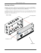
LTRx-512 Installer’s Guide Mounting the Master The Master comes ready to surface mount on the wall. However, you can also install the Master in a standard 19" rack, recess the power supply into the wall or hide the power supply in the floor or ceiling and hang only the display unit on the wall with optional hardware. A qualified electrician who understands the electrical code in your area should install your Master.
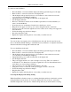
LTRx-512 Installer’s Guide To surface mount the Master • • • • • • • • • • • • Place the Master on its back with the display unit facing up and the keypad to the right Remove the two screws from just above the display unit Lift the display unit up and away from you.
LTRx-512 Installer’s Guide the ribbon cable plugged in. For Semi-Flush mounts, remove the green communications plug from the back of the display unit, so it can sit flat against the wall. Swing the two hooks on the back of the unit up and hook them over the bottom edge of the back box.
LTRx-512 Installer’s Guide Rack Mount The LTR8-512 and LTR8-512M come with two L-shaped brackets (optional on the LTR4-512) so you can install your Master in a standard 19-inch rack Power Supply Box Brackets Display Unit To install the Master in a 19-inch rack • • • • • • • • • • Place the Master on its back with the display unit facing up and the keypad to the right Remove the two screws from just above the display unit Lift the display unit up and away from you.
LTRx-512 Installer’s Guide • • • • • Using these same screws, attach an “L” bracket (or ear) Repeat to attach the other ear Mount the unit in the rack Follow the wiring steps in the next chapter before attaching the box cover Attach the furnished cover to the power supply using four 6-32 screws (two of these screws you removed from the display unit) Hidden Power Supply Mount You can hide the power supply portion of the Master above a dropped ceiling, under a raised floor or behind a wall, up to 8 feet awa
LTRx-512 Installer’s Guide Note: UL regulations require that you do NOT place high voltage (120V) and low voltage communication cables in the same conduit or through the same knockout holes • • • • • • • Follow the wiring steps in the next chapter For the cleanest installation, mount the display unit over a standard “double gang” 4-inch electrical box Route the other end of the 8-foot connection cable to this electrical box Place two #8 screws, 12 inches apart and level, ½-inch down from the top of the el
LTRx-512 Installer’s Guide Wiring the Master • Wire the display panel and power relay units for bell control and clock synchronization. Refer to the diagrams in Appendix D for more details. Until you complete this part of the wiring, do not turn on the AC power to P4, and keep the power/relay unit’s toggle switch turned “OFF” (Note: The LTR4-512 does not contain Terminal Block P3) POWER SUPPLY This is terminal block P4.
LTRx-512 Installer’s Guide • Your Master is already setup for 120VAC operation. If you need to wire it for 220/240VAC, change the jumper settings as shown in the drawings above • We recommend using stranded wire inside the Power Supply Box. Stranded wire allows for a firm connection to the Quick Connect terminals. Stranded wires are also less likely to interfere with the relay board components.
LTRx-512 Installer’s Guide Setting up the Master If you will use the Master to sync clocks, you must first use relays #7 & #8 (terminal block P1) for synching.
LTRx-512 Installer’s Guide [3][3][2][5][3][7] PASSWORD: [#] ADMINISTRATOR PASSWORD ACCEPTED Return to time and date display after 3 seconds 332537 Note that if you stop using the keypad for over 5 minutes, you must re-enter your password Set the Date and Time • Use Function [1] to set the date and time Press Display [#] SELECT FUNCTION CODE [1] SET DATE/TIME [#] ENT.DATE: MM-DD-YYYY [0]..
LTRx-512 Installer’s Guide Enable the Relays • Use Function [6] to enable any control relays that you want to use The Enable Circuits function only enables you to use certain relays. It does not turn them on. Use Function [3] or [4] to actually turn on these relays Press Display [#] SELECT FUNCTION CODE [6] [6]=ENABLE CIRCUITS [#] SELECT ACTIVE BELL ZONES 12345678 CLOCK CKTS PRESS [#] IF CORRECT [1]..[8] Enter the circuit numbers that you want to turn on or off.
LTRx-512 Installer’s Guide [#] SYSTEM TYPE CODE: NN If you are using an LTR8-512 or LTR8-512M and you chose a CLOCK1 type other than 00, you will see SELECT CLK2 CODE: NN [0]..
LTRx-512 Installer’s Guide Auto Test the Bells Use the Auto Bell Test feature to turn on all bell relays once per minute at the start of each minute. Once you start this function, you can test the continuity of your bell wiring circuits. Use the “hidden code” 2355878 [BELLTST] to start the Auto Bell Test.
LTRx-512 Installer’s Guide You cannot choose function [B] directly.
LTRx-512 Installer’s Guide Functions Defined [#] [*] Starts the Programming Functions and Confirms Entries Ends Program functions and/or Cancels Entries (except the “Quick Check”) Quick Check Commands Quick Check commands display system information for about 2 seconds. You can press any of the three quick check keys ([*], [1] or [3]) when the Master is in Clock Mode. Quick Check Command [*] Status Any time you see the time and date, you can press [*] to see the Master status.
LTRx-512 Installer’s Guide Once you enter your password, you can now program your Master until it detects that you haven’t pressed a key for 5 minutes. After that, you must re-enter your password to keep programming The administrator password 332537 [DEALER] allows you to access advanced functions. Functions that require the Administrator Password are [2] Select Clock Control, [6] Enable Circuits, [7] Daylight Savings, and [B] Communications The default user password is 000000.
LTRx-512 Installer’s Guide [5] = Schedule Changes Use Schedule Changes to run schedules at a certain date and time. This function works much like the Bell Schedule Function [4]. Enter your password, then press [#][5][#]. You can program up to 16 changes at a time [6] = Enable or Disable Circuits This function requires the administrator password Use this function to Enable and Disable bell relays during circuit wiring or maintenance.
LTRx-512 Installer’s Guide setup in function [4]=PROGRAM SCHEDULE. Enter your password, then press [#][8][#] to change a schedule [9] = Sync Clocks Use this function to quickly synchronize any secondary clocks. This function is primarily used during initial installation or if power to your LTRx-512 stayed on while power to the secondary clocks stopped. Enter your password, then press [#][9][#] [A] = Program Holidays You can enter up to 16 dates as holidays in your LTRx-512.
LTRx-512 Installer’s Guide [D] = Time Calibration (Available with Firmware Version 5.02) The Crystal Oscillator that provides the Time Base for the Master Clock is optimized for operation at 25’ C / 75’F, where it will exhibit its highest accuracy. Due to natural aging of the crystal and to installation of the Master Clock in locations that do not maintain close temperature control, the frequency of the Time-Base is apt to drift from its calibrated value, causing some deterioration in timekeeping accuracy.
LTRx-512 Installer’s Guide 1 = FASTER 2 = SLOWER To exit the Time-Base Calibration procedure, press either [#] or [*]. EXAMPLE: During installation, set the Master Clock’s time to match an accurate reference (Cell Phone display, Computer Network Time, WWVB Radio Clock, etc.). At the end of one month, compare the Master’s time against the Reference Time, to determine accuracy. If the Master were, say, 32 seconds slow, then calculate required positive correction as 32 / 10.7 = 2.99 ~ 3.
LTRx-512 Installer’s Guide Daylight Savings Codes APPENDIX A - SPECIFICATIONS ELECTRICAL: Input Voltage Input Power Memory / Quartz Time Backup Bell / Clock Control Relays Fuse MECHANICAL / ENVIRONMENTAL: Operating Temperature Weight Dimensions Mounting Options FUNCTIONAL: Secondary Clocks Supported 120 or 220 / 240 VAC @ 60Hz or 50Hz 50 VA max (less than 0.5A @ 120V) 10 year (nom.) Lithium Battery 120VAC / 28VDC, 10A , Pluggable 1 x 1.0 Amp Main (AGC1) 32°-175° F (0°-80° C) About 12 lb.
LTRx-512 Installer’s Guide Daylight Savings Codes APPENDIX B – DAYLIGHT SAVINGS COUNTRY CODES ALBANIA ANDORRA ARMENIA AUSTRIA AZERBJAN AZORES BAHAMAS BALEARIC ISLANDS BELARUS BELGIUM BERMUDA BOSNIA/HERCGVENA BRAZIL BULGARIA CANADA CHANNEL ISLANDS CHILE CROATIA CUBA CYPRUS CZECH REP DENMARK EASTER ISLAND EGYPT 02 02 02 02 02 02 08 02 02 02 08 02 13 02 08 01 12 02 06 02 02 02 02 09 ENGLAND ESTONIA FALKLAND ISLANDS FINLAND FRANCE GERMANY GIBRALTER GREECE GREENLAND HAITI HUNGARY IRAN IRAQ IRELAND ISRAEL ITAL
LTRx-512 Installer’s Guide Secondary Clock Types APPENDIX C - SECONDARY CLOCK TYPE CODES Type Description 01 01 01 01 01 01 01 01 01 01 01 01 02 02 02 02 02 02 02 02 02 02 02 02 02 02 02 03 03 04 SYNCHRONOUS WIRED LATHEM TYPE SS CINCINNATI D10 IBM 77 SERIES SIMPLEX 77 SER SIMPLEX 93-9 SIMPLEX 91-9 SIMPLEX 941-9 SIMPLEX 943-9 SIMPLEX 6310-9231 STANDARD EL D10,D12 STROMBERG 3000 3W MIN IMPULSE/59 LATHEM ISC 2W/3W CINCINNATI D2-D4 DUKANE 24 SERIES EDWARDS IMPULSE FARADAY IMPULSE IBM 75 SERIES SIMPLEX 74 SER
LTRx-512 Installer’s Guide Wiring Diagrams WIRING SECONDARY CLOCKS TYPE 01 - SYNCHRONOUS WIRED TYPES INCLUDE: Lathem Cincinnati IBM Simplex Stromberg Type SS Wall Clocks D10 (115VAC), D12 (24VAC) 77 Series 77 Series, 93-9, 91-9, 941-9, 943-9, 6310-9231 3000 All circuits should be fused or protected by a circuit breaker (10Amp maximum) TYPE 02 - THREE WIRE MINUTE IMPULSE (59TH MIN.
LTRx-512 Installer’s Guide TYPE 02 - TWO WIRE REVERSE POLARITY MINUTE IMPULSE (59 TYPES INCLUDE: Lathem Cincinnati TH Wiring Diagrams MIN.
LTRx-512 Installer’s Guide TYPE 04 - Wiring Diagrams STANDARD ELECTRIC TIME AR-2A TWO WIRE DUAL VOLTAGE All circuits should be fused or protected by a circuit breaker (10Amp maximum) TYPE 05 - THREE WIRE MINUTE IMPULSE (58TH MIN.
LTRx-512 Installer’s Guide Wiring Diagrams TYPE 06 - SYNCHRONOUS WIRED TYPES INCLUDE: Cincinnati Faraday Honeywell D8 (New Style: Motor + Solenoid) ST402A All circuits should be fused or protected by a circuit breaker (10Amp maximum) TYPE 07 - DUKANE 24F200 DIGITAL CLOCKS NOTE: THIS SELECTION IS NOT SUPPORTED ON THE LATHEM LTR8-512 OR LTR4-512 SERIES. CORRECTION FOR DUKANE 24F200 DIGITAL CLOCKS IS AVAILABLE ON THE DUKANE 24A715 SERIES MASTER CONTROL WITH SOLIDSTATE RELAYS.
LTRx-512 Installer’s Guide Wiring Diagrams TYPE 08 - RAULAND 2410 DIGITAL CLOCKS (24VAC and 115VAC) 115VAC TYPE All circuits should be fused or protected by a circuit breaker (10Amp maximum) 24VAC TYPE All circuits should be fused or protected by a circuit breaker (10Amp maximum) TYPE 09 - SIMPLEX 59TH MINUTE DUAL MOTOR TYPE 10 - SIMPLEX 45TH MINUTE DUAL MOTOR TYPE 27 - SIMPLEX 2310 DUAL MOTOR Same hourly corrections as Type 09, but with addition of 12-hour corrections, as for Type 03.
LTRx-512 Installer’s Guide Wiring Diagrams TYPE 11 - EDWARDS DUAL MOTOR All circuits should be fused or protected by a circuit breaker (10Amp maximum) TYPE 12 - CINCINNATI ‘D6’ CLOCKS All circuits should be fused or protected by a circuit breaker (10Amp maximum) 31
LTRx-512 Installer’s Guide Wiring Diagrams TYPE 14 - ELECTRONIC CODED CLOCKS Clocks run normally with 120 VAC power. For any bells or clock correction, the generator prestart relay (SK1) first turns on for the signal-generator to reach frequency. SK1 turns on at the 00 second after a programmed time or manual bell time. Then relay SK2 turns on for 3 seconds, from the 10th to the 13th second, to apply the generator signal (coded cup start signal) onto the 120 VAC.
LTRx-512 Installer’s Guide Wiring Diagrams TYPE 15 - STRAIGHT FREQUENCY Clock correction and bell circuit operations are generated by sequentially applying various frequencies onto the 120 VAC. Each bell and clock correction circuit has its own frequency. Each bell and clock correction circuit has a receiver circuit that applies the associated bell or clock frequency (3510 Hz normally used for clock signals).
LTRx-512 Installer’s Guide Wiring Diagrams TYPE 16 - THREE WIRE MINUTE IMPULSE (59 MIN) WITH 12-HOUR CORRECTION TYPES INCLUDE: Simplex 91 and 941 All circuits should be fused or protected by a circuit breaker (10Amp maximum) TYPE 16 - TWO WIRE REVERSE POLARITY MINUTE IMPULSE (59 MIN) WITH 12-HOUR CORRECTION 24 V All circuits should be fused or protected by a circuit breaker (10Amp maximum) 34
LTRx-512 Installer’s Guide TYPE 17 - Wiring Diagrams STANDARD ELECTRIC TIME AR-2 TWO WIRE DUAL VOLTAGE All circuits should be fused or protected by a circuit breaker (10Amp maximum) TYPE 17 - STANDARD ELECTRIC TIME AR-3 THREE-WIRE IMPULSE All circuits should be fused or protected by a circuit breaker (10Amp maximum) 35
LTRx-512 Installer’s Guide Wiring Diagrams TYPE 18 - NATIONAL SYNCHRONOUS WIRED TYPES INCLUDE: Dukane Rauland 240 Series 2463 Series All circuits should be fused or protected by a circuit breaker (10Amp maximum) TYPE 19 - STROMBERG SYNCHRONOUS WIRED TYPES INCLUDE: NOTE: Stromberg Lathem Synchronous Type SS Wall Clocks (modified) Lathem type SS wall clocks can run according to the above signal operation if modified to reference the minute and second hands to HH:57:16 (versus HH:59:00) and the hour
LTRx-512 Installer’s Guide Wiring Diagrams TYPE 20 - THREE WIRE MINUTE IMPULSE (44 TH MIN.
LTRx-512 Installer’s Guide Wiring Diagrams TYPE 22 - DUKANE SYNCHRONOUS WIRED All circuits should be fused or protected by a circuit breaker (10Amp maximum) TYPE 23 - CONDOR DIGITAL CLOCKS (Model 2412) TYPES INCLUDE: Condor 2412 If the digital clocks lose sync with the LTRx-512, then you can use function [9]=SYNC CLOCKS to resync them.
LTRx-512 Installer’s Guide Wiring Diagrams TYPE 23 - CONDOR DIGITAL CLOCKS (Model 2422) TYPES INCLUDE: Rauland 2422 If the digital clocks lose sync with the LTRx-512, then you can use function [9]=SYNC CLOCKS to resync them.
LTRx-512 Installer’s Guide Wiring Diagrams TYPE 23 - CONDOR DIGITAL CLOCKS (BAR-AC-4412) If the digital clocks lose sync with the LTRx-512, then you can use function [9]=SYNC CLOCKS to resync them.
LTRx-512 Installer’s Guide Wiring Diagrams TYPE 24 - EDWARDS SYNCHRONOUS WIRED CLOCKS - TYPE E1 All circuits should be fused or protected by a circuit breaker (10Amp maximum) 41
LTRx-512 Installer’s Guide Wiring Diagrams APPENDIX D - WIRING DIAGRAMS Fig. D1 - TERMINAL BLOCK ‘P4’ WIRING THE LTRx-512 FOR 120VAC (nom.) OPERATION 2 1 BLK GRN WHT 120 VAC 3 4 5 J1 6 7 8 J2 All circuits should be fused or protected by a circuit breaker (10Amp maximum) WIRING THE LTRx-512 FOR 220/240VAC (nom.
LTRx-512 Installer’s Guide Wiring Diagrams Fig. D2 - TYPICAL SIGNAL DEVICE WIRING All circuits should be fused or protected by a circuit breaker (10Amp maximum) CKT 7A & 7B Operate Together. You may use & 7Bfor Operate Together. You either of CKT these 7A circuits bells. In LTR4, these may use either of these circuits for bells. circuits become CKT 3 and CKT 4.
LTRx-512 Installer’s Guide Wiring Diagrams Fig. D3 - COMPUTER CABLE (For Front Access Port) (LTR8-512 and LTR8-512M Only) Fig.
LTRx-512 Installer’s Guide Wiring Diagrams Fig.
LTRx-512 Installer’s Guide Wiring Diagrams Fig. D7 – COMMUNICATION TERMINAL BLOCK Rear of Display Unit NOTES: 1. Twisted-pair (Cat-3/Cat-5) wire connects directly to Terminal Block; up to 2 wires per position 2. Pulse-sync input is same as provided in power supply. One (1) second (min.) dry-contact switch closure across terminals causes Master to reset time to 12:00AM of nearest date 3. Grounds (GND) are “signal grounds”, not “chassis grounds” 4.
LTRx-512 Installer’s Guide Wiring Diagrams Use the six (6) connections as follows: RS-485 Sync Time Device Connection • Sync In: Terminal block pair used to receive RS-485 synchronization from another Lathem Master product or radio sync device, or transmit the LTRx-512’s own sync commands to up to 31 RS-485 devices, including Lathem Masters and DDC4R Wall Clocks • Sync Out: Terminal block pair used to buffer and repeat a received RS-485 sync signal, or transmit the LTRx-512’s own synchronization commands
LTRx-512 Installer’s Guide Wiring Diagrams Fig. D8 - POWER SUPPLY TERMINAL BLOCKS NOTES: 1. Circuits CKT1...CKT4 designate bell controls. Circuit pairs CKT5/CKT6 and CKT7/CKT8 can function as clock synchronization circuits or as bell controls (Note: CKT1…CKT4 do not exist on the LTR4-512. Instead use CKT5…CKT8 which are indicated related to the LEDs on the Display Unit numbered 1-4). 2. MOV’s (Metal-Oxide Varistors) protect all relay contacts 3.
LTRx-512 Installer’s Guide Installing the Modem APPENDIX E – INSTALL THE OPTIONAL MODEM Installation of the optional internal modem should be performed by a trained and competent electronics technician. Follow these steps; 1. Turn off the power to the Master Clock. You can either access the on/off switch inside the Power Supply Box or turn off the power at the source. 2. Remove the four (4) screws from the sides of the Display Unit. 3. Gently remove the cover of the Display Unit.
LTRx-512 Installer’s Guide Connecting the LTR-RSS APPENDIX F – Connecting the LTR-RSS Remote Schedule Selector The “Remote Schedule Selector” is an accessory for the LTR8-512 Master Controller and allows an Operator to select one (1) of the eight (8) possible schedules stored in the Master Controller [or No Schedule] for immediate activation.
LTRx-512 Installer’s Guide Connecting the LTR-RSS INSTALLATION To install the Remote Schedule Selector, • Remove the RSS from it’s package and locate the four (4) conductor connector (upper left) and the dip switch (bottom center) on the back of the circuit board. • Set the hidden Address Selector dip switch to match the Master’s Programmed Address (default = Code 65) and the Master Clock’s baud rate. You accomplish this by sliding the dip switches towards the legend on the circuit board.
LTRx-512 Installer’s Guide Connecting the LTR-RSS INSTALLATION DETAIL 52
LTRx-512 Installer’s Guide Connecting the LTR-RSS OPERATIONAL DESCRIPTION To use the Remote Schedule Selector, the Operator will first select, via the Rotary Switch, which of the Schedules is to be made active. The ‘OFF’ position may be used to de-activate all schedules Positions ‘1’ to ‘8’ may be used to select a single Schedule to be made ‘Active’ The ‘INQUIRE’ position may be used to determine which Schedules may be currently ‘Active’ without altering those schedules previously selected.
LTRx-512 Installer’s Guide Connecting the LTR-GPS Satellite Receiver/Synchronizer APPENDIX G – Connecting the LTR-GPS Satellite Receiver / Synchronizer Lathem’s LTR-GPS is a Global Positioning Satellite receiver using 12-channels to access the accurate date and time signal transmitted each second by 24 satellites in geosynchronous orbit around the globe. The package includes an amplified GPS Antenna, which must be mounted out-doors or beneath a roof sky-light, facing skyward.
LTRx-512 Installer’s Guide Power Supply Schematics APPENDIX H – POWER SUPPLY SCHEMATICS LTR8-512 / LTR8-512M LTR4-512 (C) 2000 LATHEM TIME CORP. VMM7086 REV. D C5 D12 K7 K8 K6 D4 D3 D5 D6 K5 K6 K7 D6 D5 D4 D3 K8 55 K5 D11 D10 D9 D12 D11 D10 D9 K4 K3 C3 C3 K2 C4 C4 C5 K1 (C) 2000 LATHEM TIME CORP. VMM7086 REV.
LTRx-512 Installer’s Guide Power Supply Schematics FOR UNITS EQUIPPED WITH AN INTERNAL MODEM NOTICE: This equipment complies with Part 68 of the FCC Rules. On the mounting panel of this equipment is a label that contains, among other information, the FCC Registration Number and Ringer Equivalence Number (REN) for this equipment. If requested, provide this information to your Telephone Company. The registration jack USOC for this equipment is (RJ-11).
LTRx-512 Installer’s Guide Power Supply Schematics Limited One-Year Limited Warranty Lathem warrants the hardware products described in this guide against defects in material and workmanship for a period of one year from date of original purchase from Lathem or from an authorized Lathem reseller. The conditions of this warranty and the extent of the responsibility of Lathem Time Corporation (“Lathem”) under this warranty are listed below. 1. 2. 3. 4. 5. 6. 7. 8. 9.
LTRx-512 Installer’s Guide Power Supply Schematics A Administrator password...................... 11, 17, 18, 19, 20 Auto Bell Test ......................................................15, 22 B Baud Rate.............................................................16, 17 Bell schedules................................................... 1, 18, 19 Bell zones...................................................................11 C Cable connection ..........................................................