
Time Systems Master Clock Installer's Guide


LTRx-512 Installer’s Guide
Wiring Diagrams
48
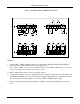
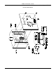
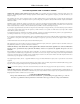
Fig. D8 - POWER SUPPLY TERMINAL BLOCKS
NOTES:
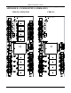
1. Circuits CKT1...CKT4 designate bell controls. Circuit pairs CKT5/CKT6 and CKT7/CKT8 can
function as clock synchronization circuits or as bell controls
(Note: CKT1…CKT4 do not exist on the LTR4-512. Instead use CKT5…CKT8 which are indicated
related to the LEDs on the Display Unit numbered 1-4).
2. MOV’s (Metal-Oxide Varistors) protect all relay contacts
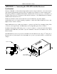
3. Voltage-select jumpers connect to terminal block P4 for 120VAC operation. Users who need to run
at 220/240VAC must remove the 120V jumpers and install one jumper wire for the 240V selection.
The system will automatically adjust for operation at 60Hz or 50Hz at either voltage
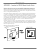
4. Some clock setups may require external diodes or MOV’s. See the wiring diagram for your type
clock