PC100 Terminal Installation & User’s Guide
PayClock, Lathem and the Lathem logo are registered trademarks of Lathem Time Corporation. Other product names mentioned in this manual may be trademarks of their respective companies and are hereby acknowledged. Warning: Changes or modifications to this unit not expressly approved by the party responsible for compliance could void the user’s authority to operate the equipment.
Limited One-Year Limited Warranty Lathem warrants the hardware products described in this guide against defects in material and workmanship for a period of one year from date of original purchase from Lathem or from an authorized Lathem reseller. The conditions of this warranty and the extent of the responsibility of Lathem Time Corporation (“Lathem”) under this warranty are listed below. 1. 2. 3. 4. 5. 6. 7. 8. 9.
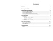
Contents Welcome 1 Mounting the PC100 2 Connecting to the Computer 4 Connecting the PayClock via RS-232 ..................................................................................................... 4 Connecting Terminals via RS-485........................................................................................................... 4 Connecting Terminals via RS-485 (Star Configuration) .........................................................................
PC100 Terminal User’s Guide CHAPTER 1 Welcome Reliability, functionality and ease of use are trademarks of the PayClock terminal. With the PC100 terminal, employees use their plastic ID badges to punch in and out – it’s that simple. Using Lathem software and your computer, the PayClock terminal is the perfect solution for businesses that want to track employee time and automate payroll.
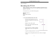
PC100 Terminal User’s Guide CHAPTER 2 Mounting the PC100 Check your package contents to make sure everything is accounted for before starting. Decide where to mount your clock. Keep in mind that the AC adapter plugs into a wall outlet. To mount the clock, you need the following items: Drill with a 5/16” bit Hammer Phillips head screwdriver Pencil 1.
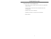
PC100 Terminal User’s Guide 2.
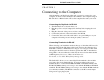
PC100 Terminal User’s Guide CHAPTER 3 Connecting to the Computer After mounting your PayClock on the wall, you need to connect it to your computer. You can connect the PayClock terminal to the computer using an RS-232 cable or RS-485 cable. Choose the setup that best suits your needs. Connecting the PayClock via RS-232 1. Turn the PayClock so its back faces you 2. Plug the power cord (AC adapter) into the PayClock, keeping the cord slack 3. Plug the other end of the power cord into a wall outlet 4.
PC100 Terminal User’s Guide Use either connection RS485 Power to terminals + ~ ~ RJ11 RJ45 PC100 PC2000 PC2500 RS485 RS485 ~ ~ + - POWER LED’s RS232 RS232 to PC Use either connection Power to terminals RS485 SWIFT-485 plus Connecting Terminals via RS-485 (Star Configuration) A star network connects up to 31 terminals or sync time devices to the computer. You can wire the terminals directly to the SWIFT-485+ or use Jkits (junction boxes).
PC100 Terminal User’s Guide 4. See the Cable Wiring Diagrams for detailed connection points Connecting Terminals via RS-485 (Multi-Drop Configuration) A multi-drop network connects up to 31 terminals or sync time devices to the computer. You wire the terminals to junction boxes running in a single line starting from the SWIFT-485+. Terminals can be located up to 4000 feet from the computer Up to 31 Terminals Max 4000 ft from SWIFT-485+ to Last Terminal SWIFT-485+ J-Kit (junction box) 1.
PC100 Terminal User’s Guide CHAPTER 4 Using the PC100 The base model PC100 clock allows only an RS-232 connection. The PC100-R model allows RS-232 or RS-485 connections; RS-485 connections require the Terminal Manager software add-on. The PC100 has a magnetic stripe badge reader. The magnetic stripe should be on the left side of the badge when swiping. To swipe the badge, insert it at the top of the reader, and then pull it down with a continuous and smooth motion.
PC100 Terminal User’s Guide ♦ PC100 version number ♦ Terminal ID# (ID=49) ♦ Percent full memory (each time you poll the clock, this resets to 0%) ♦ Clock ready status (READY/LOAD LIST) ♦ Baud Rate ♦ 12-Hour or 24-Hour time display format ♦ Daylight Savings Time (DST) ON/OFF After a few seconds, the display returns to normal. Badge #253 – Set Baud Rate Swipe this badge to change the baud rate – the default is 9600.
PC100 Terminal User’s Guide Specifications Casing: 6.375”W x 7.375”H x 1.5”D flame-retardant ABS plastic. 19 oz. Includes key lock and wall mounting bracket Power: 6VDC/ 300 mA wall-mount power supply. UL approved Display: 4 lines x 20 characters liquid crystal with large block digits Swipe Status: “Beeper” signals good or bad badge reading and low memory.
PC100 Terminal User’s Guide APPENDIX A Cable Wiring Diagrams RS-232 (Computer to PC100) 10
PC100 Terminal User’s Guide RS-485 Multi-Drop PayClock PayClock See Fig. A Be sure to maintain polarity through out the chain Fig.
PC100 Terminal User’s Guide Junction Box to Terminal 12
PC100 Terminal User’s Guide APPENDIX B Troubleshooting PC100 Description When I swipe a badge, it does not record and the clock does not signal any errors Solution Make sure you swiped the badge correctly. See the section on Using the PC100 Or This badge may have been exposed to something magnetic.
PC100 Terminal User’s Guide INDEX B S Badges................................................... 7 Baud Rate.............................................. 8 Bracket .............................. See Mounting Bus Configuration................................. 6 Cable ..................................................... 4 Screws ............................... See Mounting Special Badges ...................................... 7 Specifications PC100 ................................................