
Assembling & Installation Instructions

ASSEMBLING
ASSEMBLING
ASSEMBLING
ASSEMBLING &
&
&
& INSTALLATION
INSTALLATION
INSTALLATION
INSTALLATION INSTRUCTIONS
INSTRUCTIONS
INSTRUCTIONS
INSTRUCTIONS
For
For Wall
Wall
Wall
Wall Mount
Mount
Mount
Mount Light
Light
Light
Light Fixture
Fixture
Fixture
Fixture
WARNING! SHUT POWER OFF AT FUSE OR CIRCUIT BREAKER .
MOUNTING
MOUNTING
MOUNTING
MOUNTING THE
THE
THE
THE FIXTURE
FIXTURE
FIXTURE
FIXTURE
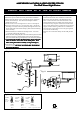
Installation (see fig.1)
1.Disconnect power at main electrical panel before installation.
2. Mount the back plate (F) to the wall with the plastic anchors( E )
and the wood screw (G) . The side of the back plate marked
“ GND ” must face out.
3 .Guide fixture wires through hole in center of back plate.
4 . Place the fixture body ( C ) over the back plate , thread the
mounting screws (D) to the back plate(F) ,through the hole in the
f ixture back plate of the fixture body( C ),then lock the mounting
screws securely.
5. Raise the shade( A ) to bottom of the lamp socket
,
then lock
it securely with ring ( B ) until su n g .
6. Mount the short back plate (H) to the wall with the plastic anchors
and the wood screw , feed the fixture wires into the short back
plate, then attach the long back plate(I) to the short back plate(H).
7.
7.
7.
7. If
If
If
If you
you
you
you not
not
not
not need
need
need
need assembly
assembly
assembly
assembly the
the
the
the fixure
fixure
fixure
fixure lamp
lamp
lamp
lamp ,
,
,
, please
please
please
please pause
pause
pause
pause and
and
and
and
Take
Take
Take
Take out
out
out
out fixture
fixture
fixture
fixture wires
wires
wires
wires nuts
nuts
nuts
nuts of
of
of
of the
the
the
the back
back
back
back plate
plate
plate
plate ,
,
,
, then
then
then
then
f
f
f
f ollow
ollow
ollow
ollow wiring
wiring
wiring
wiring instructions
instructions
instructions
instructions carefully
carefully
carefully
carefully .
.
.
. (see
(see
(see
(see fig.2
fig.2
fig.2
fig.2 and
and
and
and fig.1.1
fig.1.1
fig.1.1
fig.1.1 )
)
)
)
8 .Install the light bulbs in accordance with the fixture ’ s
specifications. DO
DO
DO
DO NOT
NOT
NOT
NOT EXCEED
EXCEED
EXCEED
EXCEED THE
THE
THE
THE MAXIMUM
MAXIMUM
MAXIMUM
MAXIMUM
WATTAGE
WATTAGE
WATTAGE
WATTAGE RATING!
RATING!
RATING!
RATING!
Wiring (see fig.2)
2.Tuck the wire connections neatly into the wall junction
box.
F ig.1
I
H
Fig. 2
White or
HOUSE
Black
WIRES
(Hot)
Smooth
FIXTURE
WIRES
Black or
Ribbed
WIRES
FIXTURE
Bare Copper(Ground)
FIXTURE
WIRES
Copper
(Ground)
HOUSE
(Neutral)
WIRES
White
Bare
Green or
WIRES
HOUSE
F ig.1 .1
Listed
U
L
R
For
For
1.Connecttheelectricalwiresasfollows.Connectthe
Blackwirefromthefixturetotheblackhouse(hot)
Wire.Connectthewhitewirefromthefixturetothe
white(neutral)housewire.Makesureallwirenutsare
secured.
You
maywraptheconnectionswithelectrical
tape.Ifyouroutletboxhasagroundwire(greenorbare
copper)connectfixture
’
sgroundwiretoit.Otherwise
attachthebarecopperfixturewiretothegreenground
screwonthecircularstrap.