
User's Manual


LAUNCH X-431Diagun User's Manual
3
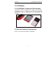
Figure 2-2 X-431Diagun main unit ports and indicators
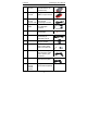
Diagram 2-1 X-431Diagun ports and indicators
A
Diagnostic Connector
B
Diagun Connector
C Blue Tooth LED (blue)
D
Power LED (red)
E
12PIN Port F
Lanyard Eyelet
G Diagnostic Interface H
Earphone Hole & TF Card Slot
I Power Button J
Diagun Main
K
Touch Screen L
Stylus Holder
M Main Back N
Buzzer
O Reset Button P
Battery Cover
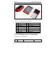
2.3 X-431Diagun General Components
Diagram 2-2 is for each component
No. Name Description Picture