
User Manual


LAUNCH
CReader Series English User’s Manual
2
cable. The memory card is highly recommended to update your tool.
Note: CReader 6011/7001/7001F/8001/8011/8021/9081 may automatically reset while
being disturbed by strong static electricity. THIS IS A NORMAL REACTION.
2. General Information
2.1 On-Board Diagnostics (OBD) II
The first generation of On-Board Diagnostics (OBD I) was developed by the
California Air Resources Board (ARB) and implemented in 1988 to monitor some
of the emission control components on vehicles. As technology evolved and the
desire to improve the On-Board Diagnostic system increased, a new generation of
On-Board Diagnostic system was developed. This second generation of
On-Board Diagnostic regulations is called “OBD II”.
The OBD II system is designed to monitor emission control systems and key
engine components by performing either continuous or periodic tests of specific
components and vehicle conditions. When a problem is detected, the OBD II
system turns on a warning lamp (MIL) on the vehicle instrument panel to alert the
driver typically by the phrase of “Check Engine” or “Service Engine Soon”. The
system will also store important information about the detected malfunction so
that a technician can accurately find and fix the problem. Here below follow three
pieces of such valuable information:
1) Whether the Malfunction Indicator Light (MIL) is commanded ‘on’ or ‘off’;
2) Which, if any, Diagnostic Trouble Codes (DTCs) are stored;
3) Readiness Monitor status.
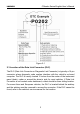
2.2 Diagnostic Trouble Codes (DTCs)
OBD II Diagnostic Trouble Codes are codes that are stored by the on-board
computer diagnostic system in response to a problem found in the vehicle. These
codes identify a particular problem area and are intended to provide you with a
guide as to where a fault might be occurring within a vehicle. OBD II Diagnostic
Trouble Codes consist of a five-digit alphanumeric code. The first character, a
letter, identifies which control system sets the code. The second character, a
number, 0-3; other three characters, a hex character, 0-9 or A-F provide additional
information on where the DTC originated and the operating conditions that caused
it to set. Here below is an example to illustrate the structure of the digits: