
Installation Manual

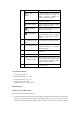
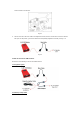

indicator
USB status
indicator
It illuminates blue after USB cable is
properly connected to X-431 HD
module. (Currently disabled, for
subsequent function extension.)
Wi-Fi indicator
It lights up when Wi-Fi / Bluetooth toggle
switch is in Wi-Fi mode.
Bluetooth indicator
It lights up when Wi-Fi / Bluetooth toggle
switch is in Bluetooth mode.
Battery working
indicator
Press the power switch, it will light up;
To put it out, press it again.
Charging indicator
It illuminates green while being charged;
once fully charged, it goes out. (Note: In
general, the charging time is about 1-2
hours.)
2
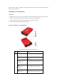
Wi-Fi / Bluetooth toggle
switch
To toggle between Wi-Fi and Bluetooth.
3
PC communication port
To connect to the serial port of PC.
(Currently disabled, for subsequent
function extension.)
4
USB port
To connect the B-shaped terminal of
USB cable.
5
Diagnostic socket
To connect the main cable.
6
Power switch of Wi-Fi
and Bluetooth module
To turn on/off the power supply of Wi-Fi
& Bluetooth module. (Note: This switch
is not intended to manage the power
supply of X-431 HD module.)
7
Power interface
To connect the power adaptor of
X-431HD module.
1.3 Technical Parameters
Working voltage: 8~24V
Working temperature: -15℃ ~ 60℃
Storage temperature: -20℃ ~ 70℃
Relative humidity: 10% ~ 80%
Dimension: 110 mm * 178 mm * 50 mm
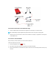
2 Connections
2.1 How to connect OBD II vehicle
Follow the steps described below to proceed:
1. Locate vehicle’s DLC socket. The DLC is usually located 12 inches from the center of the instrument panel
(dash), under or around the driver’s side for most vehicles. If Data Link Connector is not located under
dashboard, a label should be there telling location. If the DLC cannot be found, refer to the vehicle’s