
User Guide

+
-
Quick Start Guide
All pictures and descriptions illustrated herein are for reference purpose
only and this Quick Start Guide is subject to change without notice.
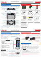
X-431 PAD V Tablet Accessory Checklist
X-431 PAD V Tablet
A tablet for showing
test results.
Docking Station
See Section “Docking
Station” .
VCI Device
A device for accessing
vehicle data.
Type-C Charging Port
Charging Slot
Data Transmission Port
Memory Card Slot
Ambient Light Sensor
Charging Indicator
Microphone
Microphone
Front Camera
Power/Screen
Lock Button
Volume Buttons
10.1" Touch Screen
Camera Flash
Rear Camera
Audio Speaker
Adjustable Kickstand
Audio Speaker
(Reserved for and
other USB devices use only.)
add-on modules,
( )Reserved for charging or transferring data.
(
for storage extension.)
To store the memory card
(
placing it on the docking station)
For charging the tablet via
(Red means Charging, and
Green means Fully Charged.)
(
)
Flip out it to any angle and work comfortable
at your desk, or hang it on steering wheel.
LAUNCH
Power Adaptor
To supply power to the tablet
through connection to AC
outlet.
OBD I Adaptor Cable
A converting cable for
connecting non-16 pin
connector.
Cigarette Lighter Cable
To supply power to the non-
16pin connector via vehicle’s
cigarette lighter receptacle.
Battery Clamps Cable
To provide power to the non-
16pin connector through
connection to the vehicle’s
battery.
Private & Confidential Sheet
A piece of paper bearing
Product S/N and Verification
Code, which is required for
your VCI activation.
OBDII Extension Cable
To connect the VCI device
for extension purpose.
Non-16pin Adaptor Kit
(Optional. For different
vehicle diagnostic sockets, it
may be necessary to use one
of the connectors/adaptor
cables included within the
kit. For detailed non-16pin
connectors, please check the
package box)
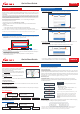
VCI(Vehicle Communication Interface) Docking Station
1. Charging & Turning On
The VCI device works as a vehicle communication interface device, which is used to connect to
the vehicle's DLC (Data Link Connector) socket via OBD II extension cable to read the vehicle
data and then send it to the tablet via Wi-Fi. It can work with the passenger & commercial
vehicles.
(Plug the VCI device into the socket for demo experience via OBD II
extension cable when the docking station is connected to the AC outlet.)
Charging Slot
OBD 16 Socket with power output
(To charge the tablet.)
Choose any of the followings to charge it:
1. Use the included power adaptor: Connect one end of the adaptor to Type-C charging port of
the tablet, then connect the other end to the AC outlet.
*Warning: Please use the included power adaptor to charge the tablet. No responsibility can be
assumed for any damage or loss caused as a result of using power adaptors other than the one
supplied.
2. Use the docking station: Follow the steps described as below to charge the tablet:
a). Locate the charging slot on the tablet and the docking station.
b). Align the charging slots, and then dock the tablet into the station to ensure that it firmly
sits on the docking station.
c). Insert one end of power adaptor into the Type-C charging port of the docking station,
then plug the other end into the AC outlet.
3. Press the [POWER] button on the tablet, the system starts initializing and then enters the home
screen.
*Note: If the battery remains unused for a long period of time or the battery is completely
discharged, it is normal that the tablet will not power on while being charged. Please charge it for a
period of 5 minutes and then turn it on.
LAUNCH
DC OUT5V Port
Type-C Charging Port
Power Indicator
(Illuminates red when it is powered up.)
(Reserved for
other USB devices only.)
charging
(To supply power to the
docking station through
connection to AC outlet.)
LED Indicators
It is defined as follows:
1. Power: It illuminates solid red when the module is
powered on.
2.Vehicle: While communicating with the vehicle, the
indicator lights up and flashes. Otherwise, it will not
illuminate.
3.BT: It illuminates when the VCI device is working in
wireless BT communication mode.
4. I/O: It lights up when the VCI device is connected to the
tablet via data cable.
5. Wireless: It illuminates when the VCI device is working
in default WLAN communication mode.
(To connect on vehicle's OBD II DLC.)
OBD-16 connector
Data I/O port
(
vehicle diagnosis via data cable.)
To connect it to the tablet to perform
Technical Parameters:
Working voltage: 9~36V
Available communication mode:
1) Wireless
2) Data cable
*Note: When the VCI device is
connected to the tablet via data
cable, the system will switch to USB
mode automatically and the Wireless
communication becomes disabled.
*Note: When connecting the non-OBD II
vehicle’s DLC, please check the type of the
DLC and select the corresponding non-
16pin connector or adaptor cable. After use,
please remember to unplug it from the
vehicle’s DLC.
DC-IN power jack
(For connecting the power adaptor.)
Reset hole
(To reset the VCI device.)
Quick Start Guide