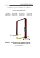
LAUNCH TECH USA INC. LAUNCH Installation, Operation & Maintenance Manual Two Post Surface Mounted Lifts TLT210-A TLT210-AS TLT210-XT TLT211-AS 10,000 lb. Capacity 2,500 lbs. per Arm 10,000 lb. Capacity 2,500 lbs. per Arm 10,000 lb. Capacity 2,500 lbs. per Arm 11,000 lb. Capacity 2,750 lbs. per Arm Model TLT210-AS pictured IMPORTANT: 1820 S Milliken Ave. READ THIS MANUAL COMPLETELY BEFORE INSTALLING OR OPERATING YOUR LIFT Ontario, California 91761 Telephone: 562 463-1580 www.launchtechequipment.
OWNER / EMPLOYER OBLIGATIONS 1.
7. The Owner/Employer shall not modify the lift in any manner without the prior written consent of the manufacturer. IMPORTANT SAFETY INSTRUCTIONS 1. When using this lift, basic safety precautions should always be followed, including the following: 2. Read all instructions in this manual and on the lift thoroughly before installing, operating, servicing or maintaining the lift. 3. Care must be taken as burns can occur from touching hot parts. 4.
13. Use only as described in this manual. Use only manufacturer’s recommended attachments. 14. ALWAYS WEAR SAFETY GLASSES. Everyday eyeglasses only have impact resistant lenses, they are not safety glasses. 15. Inspect lift daily. Do not operate if it malfunctions or problems have been encountered. 16. Never attempt to overload the lift. The manufacturer’s rated capacity is shown on the identification label on the power side column. Do not override the operating controls or the warranty will be void. 17.
28. Do not remove hydraulic fittings while under pressure. WARNING! Failure by purchaser to provide the recommended mounting surface could result in unsatisfactory lift performance, property damage, or personal injury. LOCATION This lift has been evaluated for indoor use only with an operating ambient temp.
SAFETY AWARENESS REFERENCE: AUTOMOTIVE LIFT INSTITUTE (ALI) SAVE THESE INSTRUCTIONS Note: Some images in this manual are generic and may not resemble the lift you have purchased.
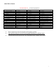
SPECIFICATIONS LAUNCH TECH USA A. B. C. D. E. F. G. H. I. J. Maximum Lifting Height Minimum Column Height Cylinder Full Height Total Width Drive-Thru Clearance Floor to Overhead Switch Front Arm Reach (min / max) Rear Arm Reach (min / max) Screw Pad Height Inside Column Width Electric Hydraulic Power Unit Voltage Rise Speed Max. Load Per Arm Minimum Ceiling Height Required Narrow Bay Setting Maximum Column Height Power Unit Operating Pressure TLT211- AS 11,000 lb. Capacity 75.
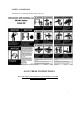
PACKING LIST The complete lift is contained in two (2) packages: 1. The main structural components and parts are packed in a steel frame. 2. Power Unit Box including Shutoff Switch and all Documents Main Structural Components and Parts 1pc. - Power side tower and carriage assembly 1pc. - Slave side tower and carriage assembly 1pc. - Overhead Beam 1pc. - Actuator Bar w/ foam 1pc. - Power side column extension 1pc. - Slave side column extension 2pc. - Two front arm assembles (Three piece design) 2pc.
INSTALLATION REQUIREMENTS AND TOOLS FOUNDATION IMPORTANT: It is the user’s responsibility to provide a satisfactory installation area for the lift. Lifts should only be installed on level concrete floors with a minimum thickness of four inches (4") or 102 mm. Concrete must have a minimum strength of 3500 psi should be aged thirty (30) days prior to installation.
INSTALLATION INSTRUCTIONS When the lift arrives on site: Read the owner’s manual and make sure the installation instructions are fully understood. Check for any freight damages. The shipment should be thoroughly inspected as soon as it is received. The signed bill of lading is acknowledgement by the carrier of receipt in good condition of shipment covered by our invoice .
BAY LAYOUT IMPORTANT: Always wear PPE (Personal Protection Equipment) when installing or servicing a vehicle lift. Prepare the bay by selecting the location of the lift relative to the walls. Clear the installation area of all packaging materials to avoid trip hazards. Measure midpoint of door. Using measuring tape, scribe two arcs, equal distance from the midpoint. The centerline of the lift occurs between the intersection of the arcs and the midpoint of the door.
Figure 3 TLT210-AS or TLT210-XT Bay Layout Deduct 150mm/5.9 in.
Figure 4 TLT210-A or TLT210-XT Bay Layout Deduct 150mm/5.9 in.
Figure 5 TLT211-AS Bay Layout Note: There is no narrow bay setting on the TLT211-AS 14
COLUMN ASSEMBLE Assemble the column extensions and the positive carriage stop brackets to each column using 12 sets of 12x35 hex bolts, flat washers, lock washers and nuts. Repeat for opposite column and extension. Determine if the lift will be in the tallest or lowest position at this time. Note that the TLT211-AS column extensions are already assembled and may be preassembled at either the short or tallest position.
Refer to Bay Layout Figures about to ensure that the column is still in the proper position before the anchor bolts are installed Prior to installing anchors, assemble the nut and washer onto anchors. A minimum of six threads must be visible below the surface of the nut. Refer to the figure below while reading through the following instructions. Using a ¾” concrete drill bit and rotary hammer drill, drill ¾” holes for the anchor bolts on the power side column. Drill through the concrete floor.
INSTALLING THE OVERHEAD BEAM After positioning the slave column at the designated chalk location; assemble the overhead beam on the shop floor to either the narrow or widest lift width hole positions as determined by the chalk line measurements. See the photo below for illustration. Photo below shows the overhead beam assembled at the widest (most common) position. While the overhead beam is still on the shop floor install the provided 4 pulleys (sheaves).
ASYMMETRIC PULLEY INSTALLATION Use the 4 pulleys (sheaves) located in the parts packaging combined with the parts in the packet marked “Asymmetric Installation” to install the pulleys for an Asymmetric configuration. Below is what is contained in the asymmetric parts packet. No. Name and Specs Part Number Qty.
Asymmetric Pulley Configuration Continued…. The photo below illustrated the proper alignment and placement of the pulleys into the overhead beam. Note that the outer pulley is positioned on the overhead beam in the outer most axle holes and that it is closest to the front of the lift. The inner pulley is positioned in the inner most axles holes and is mounted toward the rearward area of the lift.
SYMETRIC PULLEY INSTALLTION Use the 4 pulleys (sheaves) located in the parts packaging combined with the parts in the packet marked “Symmetric Installation” to install the pulleys for a Symmetric configuration. Below is what is contained in the symmetric parts packet. No. Name and Specs Part Number Qty.
Symmetric Pulley Installation Continued… The photos below illustrate the proper alignment and placement of the pulleys (sheaves) into the overhead beam. Note that both pulleys are positioned on the overhead beam sharing a common axle and the axle is positioned in the outer most axle holes and that is closest to outer most area of the overhead beam. Install both sets of pulleys on each end of the over beam to exactly match each other.
SYMETRIC OVERHEAD BEAM INSTALLATION Lift the overhead beam to the level of the column tops and use the fasteners to attach it to the upper columns and the transitional brackets. If you are installing for a Symmetric configuration the column mounting bolts must be aligned as show below.
INSTALLING THE PADDED SAFETY BAR AND SHUTOFF SWITCH Install the safety shut-off electrical switch to the bracket on the underside of the overhead beam adjacent to the power unit column. Use the provided shoulder bolt and cotter pin to attach to the bracket and then route the electrical cord up into the overhead beam via the small hole next to the bracket. When this is done the shut-off switch will be in a vertical position.
INSTALLING THE EQUALIZATION CABLES Note: For the widest and tallest configuration the cables must be connected to the lowest innermost hole inside the carriage. For either the narrow or shortest configuration the cables must be connected to the middle hole inside the carriage. For both the narrow and shortest configuration the cables must be connected to the top hole inside the carriage and you must use the cable tube extensions (They look like a 1”x6” diameter pipe) so the cable bolts can be tightened.
HYDRAULIC HOSE INSTALLATION Refer to the drawing below for the hydraulic hose location. Please reference the hydraulic hose instructions preceding the drawing.
Hydraulic Hose Installation continued… After referring to the drawing above install the hydraulic hoses in this sequence. Notice: DO NOT USE TYFLON TAPE ON ANY HIGH PRESSURE FITTTINGS. THIS ABOVE GROUND TWO POST LIFT UTILIZATES ONLY HIGH PRESSURE HYDRAULIC OIL FITTINGS. TYFLON TAPE IS ONLY DESIGNED FOR LOW PRESSURE WATER PIPE. Use only high pressure oil sealant compound to the male and female threads.
SAFETY SHUTOFF SWITCH It is very important to keep proper clearance between shutoff switch electrical cord and the steel cable. Use the provided plastic ties to connect the electrical cord and hose together to avoid any possible damage caused by interference between the electrical cord and the steel cable.
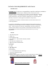
POWER UNIT INSTALLATION 1) 2) 3) 4) 5) 6) Remove the power unit from the shipping box. Remove the red plastic plug on the oil tank. Remove the black breather cap on the lower section of the oil tank. Install the black breather cap into the fill hole at the top of the tank. Install the red plastic plug into the hole at the bottom of the tank. After removing the plastic plug on the side of the power unit valve body install the 90 degree hydraulic fitting using high pressure sealant compound.
CONNECTING THE POWER SUPPLY 1) A certified electrician must connect the 230Volt/1Ph power unit and the overhead Shutoff Switch to the electrical supply. 2) Remove the sealed cover on the electrical junction box on the power unit and connect the wiring according to the wiring diagram. See Figure 9 3) A power supply switch is required to be installed near the lift for rapidly disconnecting the electrical power supply during maintenance or in case of emergency.
HYDRAULIC SYSTEM BLEEDING Crack the bleeder valve located at the top of both cylinders (approx. ¼ turn) Power up 2”-3”. You should hear air escaping around the bleeder valve. Repeat 3 – 4 times or until only oil is coming out of the bleeder valve. Tighten the bleed screw and lower the lift and recheck oil tank level.
After bleeding the hydraulic system and checking for leaks, install all of the metal hose covers. In the parts box you will find small threaded bolts with the top of the bolt drilled and taped. Install these bolts into the predrill holes on the side of each column. On the power unit side at the hydraulic “T” fitting a special hose cover with a cutout to allow for the “T” connectors shall be used.
SAFETY RELEASE CABLE ROUTING AND ADJUSTMENT The mechanical safety automatically engages. To release the mechanical safety, you must first raise the lift approximately 2”, and then pull the safety release lever down. This disengages the power side safety locks and activates the safety cable to release the slave side safety lock.
Attach the two (2) provided white nylon cable guides using the retaining rings onto the horizontal metal post just above the carriage locking mechanism on the slave side column. Inspect the metal post for any paint overspray and clean with sandpaper if necessary. Use a small amount of general purpose grease on the metal post prior to installing these cable guides. Attach the steel cable to the large metal post on the slave side column side using the provided cable clamps. See the photo below for reference.
Power Unit Column Adjust the slack in the single point lock cable at the power unit side so that when the release lever is pulled down both carriage locks will disengage. Tighten the cable clamps and install the carriage lock covers on each side with the four (4) provided screws. (Factory tip: Adjust the cables to release the locks just before the lock release lever has reached maximum travel…this prevents overstretching the cable).
FOOTPAD EXTENSION STORAGE Attach the two (2) footpad extension storage brackets one to each column using the two (2) metal screws. Store the footpad extensions as show in the photo below. At this time operate the lift up and down 2-3 times and re-adjust the equalization cables if needed so the carriage locks engage equally.
FINAL CHECK OF ASSEMBLED LIFT 1. Final dimension check after anchoring 2. Check for hydraulic leaks. 3. Ensure cables are properly routed and free from obstructions. 4. Check jam nuts on cables are tightened. 5. Check for oil leaks. 6. Check adjustment of safety release cable to ensure both sides are working properly. 7. Re-check level of towers. 8. Check torque of anchor bolts. 9. Check all fasteners, tighten if necessary. 10. Check shut off at top of stroke to ensure lift shuts off. 11.
1. Position arms to drive-thru position. 2. Refer to supplied literature prior to loading vehicle. Center the vehicle between the lift posts. 3. Only lift the vehicle on the manufacturers recommended lift points. Refer to supplied lift points guide (reference ANSI/SAE J2184-1992). 4. Locate lift pads on auto manufacturer's recommended lift points. Once you have correctly positioned the lift arms, ensure that all arm restraints are properly engaged. 5.
OPERATION TEST WITH VEHICLE Prior to starting this section, please refer to Section 2 of this manual for important safety instructions. 1. Lower lift to ground. 2. Drive vehicle on to lift and locate the arms as per the “Lift it Right” manual. 3. Raise lift to and lower onto 3-4 lock positions during full rise to ensure all locks are working correctly. 4. Re-adjust cables if necessary while vehicle is on. 5. Check lowering speed and smooth decent rate. 6. Lower lift to ground and drive vehicle off lift.
MAINTENANCE GUIDELINES SAFETY INSTRUCTIONS Refer to Section 2 for more Safety Instructions. Read operating and safety manuals before using any lift. Do not operate a lift that has been damaged or is in disrepair. Proper inspection and maintenance is necessary for safe operation. PERIODIC MAINTENANCE DAILY: 1. Check all hydraulic lines and fittings for pinch points , damage , cracks or leaks 2. Check all electrical wiring for pinch points , cracks or damage 3.
WIRE ROPES Wire ropes are critical to safe and reliable performance of your lift. Cables are expendable items and should be replaced as a set.
WIRE ROPE REPLACEMENT CRITERIA: If any cable is found to be in need of replacement, the entire cable set, pulleys and safety rollers must be replaced immediately. See cable conditions guide. In the following table, "lay" means the distance measured along a line parallel to the axis of the rope in which the strand makes one complete turn about the axis of the rope, or the wires make a complete turn about the axis of the strand.
WIRE ROPE LUBRICATION Lubricate wire ropes with lift in both lowered and raised position, by spraying them with wire rope lubricant (i.e. 2001 MONOLEC®) and wiping the cable down. WIRE ROPE ADJUSTMENT Adjust cables if lifting is uneven or lift is not level (See chapter 7.15.3). Never make adjustments with weight on lift. If running out of adjustment threads, cables need to be replaced. Do not add washers or other spacers to re-use previously used adjustment threads.
MAINTENANCE SCHEDULE Maintenance and Training Performed Date By Notes 44
TROUBLESHOOTING GUIDE PROBLEM Power Unit (Motor) not running. REASON Bad Fuse or Circuit breaker. Incorrect voltage to motor. Improper wiring. Power Unit (Motor) runs but lift does not go up. Power Unit up switch not functioning. Overhead Microswitch not functioning. Power Unit motor burned out. Low oil level. Lowering valve remains open. Pump sucking air. Lift goes up slowly or oil coming out from filler cap. Lift doesn’t come down. Air in hydraulic fluid lines Safety Locks do not engage.
LOCK OUT AND TAG OUT INSTRUCTIONS IMPORTANT: This machine does not have integral devices that will isolate the electrical, pneumatic, stored and hydraulic energy source. Appropriate isolation or blocking devices must be used that have the provisions to be switched in the off position and locked in that position. ALL MAINTANANCE AND SERVICE MUST BE PERFORMED BY A QUALIFIED PERSON. ALL MAINTANANCE AND SERVICE MUST BE PERFORMED WITH THE LIFT UNLOADED.
and magnitude of energy that the lift utilizes and shall understand the associated hazards. ELECTRICAL: Located at the user control panel, press the “E-STOP” button to disconnect the raise and lower functions. ELECTRICAL ENERGY IS STILL PRESENT AT THE LIFTS ELECTRICAL PANEL WHEN THE EMERGENCY STOP BUTTON IS PRESSED. ELECTRICAL ENERGY MUST BE TURNED OFF AND ISOLATED AT THE DISCONNECT PANEL PRIOR TO PERFORMING SERVICE OR MAINTANANCE ON THE LIFT.
AT THE LIFT, PRESS THE EMERGENCY STOP BUTTON COMPLETELY TO DE-ENERGIZE THE CONTROL BUTTONS (IF APPLICABLE). ELECTRICAL 240VOLTS AT THE DISCONNECT PLANEL, PLACE THE DISCONNECT HANDLE IN OFF POSITION. ATTACH A MULTIPLE LOCUOUT DEVICE. LOCK AND TAG. ATEMPT TO RESTART THE SYSTEM, THE SYSTEM MUST NOT START. VISUALLY VERIFY OPEN DISCONNECTS AND LOCKING DEVICE INSTALLED. DANGER: LINE SIDE OF DISCONNECT REMAINS ENERGIZED PNEUMATIC UPTO 160PSI SLOWLY CLOSE LOCKOUT VALVE TO RELEASE AIR PRESSURE GRADUALLY.
EMERGENCY OPERATION: If the lift becomes inoperative in the raised position, it is best to wait until the electrical power is restored before lowering the vehicle. However, if it’s critical to safety that the lift be lowered, the following steps should be taken. WARNING: DO NOT LOOSEN OR REMOVE HYDRAULIC CONNECTIONS OR FITTINGS UNDER PRESSURE. SERIOUS INJURY OR DEATH COULD OCCUR. NOTE: Safely performing this process requires 3 people. All personnel should stay clear of the path of the lift.
PARTS VIEW AND IDENTIFICATION Part numbers with an “A” is for the TLT211-AS Model 50
107A Part numbers with an “A” are for the TLT211-AS Model 51
201 201A 205 235 Parts numbers with an “A” are for the TLT211-AS model 206 207 226 204 209 227 208 202 228 223A 223 230 215 231 234 229 217 233 210 216 214 232 224 224A 211 218 212 213 225 225A 221 219 219A 220 222 222A 52
No.
36 37 38 39 40 41 42 43 44 201014671 201014680 104130196 45 46 201014672 201014673 103030018 103060342 201011477 103260260 103260341 103020117 201014674 47 48 49 201014675 201014676 201014685 201014671 201014680 104130196 102100206 201014672 103202751 103030018 103060342 201011477 103260341 103260341 103020117 201025080 201025177 201025081 201025082 103202748 102 104120132 103 104 105 106 103202113 104120134 103100294 104120133 103100322 M-4509-0200 AC-10AH RV21 104120132 104120159 103202113 1041
202 104990132 104990132 Slide block, strengthen nylon 104990135 104990135 TLT211-AS slide block Ⅰ 104990134 104990134 204 201011855 205 206 207 208 103010473 103040122 103040123 104130191 209 210 211 212 213 214 215 103010539 103202184 103060376 103060355 103201914 103201744 201010982 216 217 218 219 103010443 103201771 103050030 201021763 201624631 104130186 103010608 201021532 201024632 201024616 201624634 201024645 201024632 201024646 201024636 104130315 201021561 103202107 103202106 1030
231 232 233 234 103050090 201014690 201014691 201011475 103010586 103050090 103203210 103203209 201011475 103010586 235 201011741 103203213 201011742 201011742 Retaining ring, 45 Long extension tube(optional) Short extension tube(optional) Positioning plate Bolt M8×12-12.