
Installation Guide


33
SAFETY RELEASE CABLE ROUTING AND ADJUSTMENT
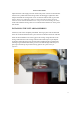
The mechanical safety automatically engages. To release the mechanical safety,
you must first raise the lift approximately 2”, and then pull the safety release lever
down. This disengages the power side safety locks and activates the safety cable to
release the slave side safety lock.
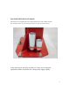
Included in the parts packaging you will find the extra-long steel single point lock
release cable, cable clamps and four (4) metal cable guides and two (2) white nylon
cable guides with two (2) small retaining rings.
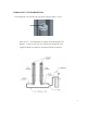
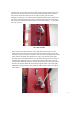
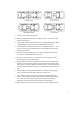
Using the provided bolts attach one metal cable guide to the inner edge at the top of
each column. Attach another metal cable guide to the outer inside edge of the
overhead beam. See the photo below for reference.
Single Point Lock Release Cable
Guides mounted to the column
and to the overhead beam. Mount
as shown to both columns. For the
TLT211-AS model a cable guide is
not used on the overhead beam.