LAUNCH TLT240SC Two Post Lift User’s Manual Version No:1605
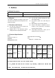
TLT240SC Two-post User’s Manual WARNING Inspect machine daily ,do not use lift with damaged parts or being damaged .Use original components to replace damaged parts The lift can’t be overloaded. The rated load of the lift is already marked on the nameplate. Please don’t raise the lift when there are people in the vehicle. During the operation, the customer and spectators shouldn’t stand in the lifting area.
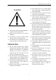
TLT240SC Two-post User’s Manual Caution Labeling Exemplification (1) (6)Use vehicle manufacturer commend lifting points! Read operating and safety manuals before using lift! (2)Proper maintenance and inspection are necessary for (7)Use bracket to help disassembly or installation! safe operation! (3)Do not operate a damaged lift! (8)Auxiliary adapters would reduce load capacity! (4)Lift can be used by trained operators ONLY! (9)Area should be unimpeded in case of vehicle overturn! (5)Only Authori
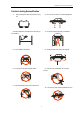
TLT240SC Two-post User’s Manual (11)Keep area clear when lifting and lowering machine! (14)Keep feet away when lowering lift! (12)Do not shake the vehicle on the lift ! (15)Do not stand under carrying arms or other load carrying device while lift is being operated with load! (13)Do not lift single side of vehicle! iii
TLT240SC Two-post User’s Manual Table of Contents 1. Outline .................................................................................................................... 1 1.1 MODEL DESCRIPTION ............................................................................................................................. 1 1.2 PURPOSE.................................................................................................................................................. 1 1.
TLT240SC Two-post User’s Manual 10.1 IMPORTANT NOTICE ..............................................................................................................................11 10.2 INSTALLATION PROCEDURE .................................................................................................................11 10.2.1 Selecting installation site .....................................................................................................................................................
TLT240SC Two-post User’s Manual 1. Outline 1.1 Model Description Model TLT240SC 4.0 clear-floor 2-post lift Description T 、Fig.2、Fig.3) clear-floor 2-post lift (Fig.1 1.2 Purpose This machine is applicable for the lifting of various small from overhead collision. and medium-sized vehicles with total weight below 4.0t in 1.3 Functions and Features Dual hydraulic cylinders drive, stable lifting and lowering. garage and workshop.
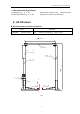
TLT240SC Two-post User’s Manual 1.5 Environmental Requirement : -5℃~+40℃ Transport/storage temperature:-5℃~+40℃ Working temperature Relative humidity: Temperature +30 Height above sea level ℃,Relative humidity 80% :No more than 2000m 2. Lift Structure 2.1 Lift structures are shown as below: : Model TLT240SC clear-floor 2-post lift 4.0 Description T 、Fig.2、Fig.3) clear-floor 2-post lift (Fig.1 2750mm(108.3in) Top beam Extension column Offside column in) Powerside column 2 .
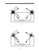
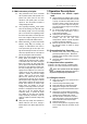
TLT240SC Two-post User’s Manual ) in .8 1in) 2 (2 . mm 44 80 0mm( 5 n= 2 mi =11 x ma ma min x= =8 13 55 65 mm mm (3 (5 3. 3. 7i 7i n) n) Passing width 2486mm(97.9in) 3420mm(134.6in) Fig.2 ) in .8 in) 2 (2 .1 mm 44 80 0mm( 5 n= 2 mi =11 x a m ma min x= =8 13 55 65 mm mm (3 (5 3. 3. 7i 7i n) n) Passing width 2415mm(95.1in) 3563mm(140.3in) Fig.
TLT240SC Two-post User’s Manual 3 Operation Descriptions 2.2 Main structure principles: Lifting mechanism: Each column is installed 3.1 Precautions for vehicle repair work with a hydraulic cylinder, when hydraulic oil is pressed from power pack into the lower chamber of main cylinder, piston rod moves upwards to drive the upward movement of carriage through leaf chain.
TLT240SC Two-post User’s Manual Note: Before operation, the safety locking devices must be inspected. 1) The gear blocks of the arm end must engage the gear block of the restraint shaft. 2) No broken strand in the steel cable. 3) No deformation in the arm pad. When lifting the vehicle, all the swing arms must be used. Before lifting the vehicle, check all the hydraulic hose and fittings for oil leakage. In case of leakage, please don’t use the lift. Remove the fitting with leakage and re-seal.
TLT240SC Two-post User’s Manual 4 Hydraulic and Electrical System of the Equipment 4.
TLT240SC Two-post User’s Manual 4.2 Electrical System of the Lift Diagram of electrical system for single phase motor AC500V20A protective switch for power needs to be prepared by customer M-Motor KM-Contactor SB1 –Button SQ- Limit switch Fig. 5 will lose the power, so the carriage will stop rising.
TLT240SC Two-post User’s Manual 5 Solutions to FAQ Symptom Reason ♦ Solution Check the circuit breaker or thermal ♦ relay for tripping Close the switch of circuit breaker or press the blue reset key of thermal relay ♦ Check the voltage to the motor ♦ Supply correct voltage for motor ♦ Check the electrical wiring ♦ Correctly wiring as electrical system ♦ ♦ Limit switch is failed Motor wire is burnt ♦ Motor rotation reversed ♦ Lowering valve body open.
TLT240SC Two-post User’s Manual Every month: Retighten the anchor bolts. Lubricate chains/cables. Check all the chain connectors, bolts and pins to 6. .Repair and Maintenance Keep clean This unit should be cleaned with dry cloth frequently ensure correct installation to keep it clean. Before cleaning, first switch off the Check all the hydraulic lines for wearing Check to see if the carriage and the inner side of the power to ensure the safety. column are properly lubricated.
TLT240SC Two-post User’s Manual Diagram of hydraulic line of clear-floor 2-post lift JB/T982-77 seal gasket 14 JB/T982-77 seal gasket 14 JB/T982-77 seal gasket 14 7. Storage and Scrap 7.1 Storage protection When the equipment requires long-time storage: Disconnect the power supply 7.2 Scrap Lubricate all the parts requiring lubrication: mobile When the equipment service life is expired and can no contact surface of the carriage, etc.
TLT240SC Two-post User’s Manual test the concrete thickness at each site by drilling test. 10. Installation If several lifts are installed at one place, it is preferred 10.1 Important notice to make drilling test in each site. The wrong installation will cause the lift damage or Power supply: Get ready the power supply before the personal injury. The manufacturer will not undertake installation.
TLT240SC Two-post User’s Manual chalk line, and mark the total width (B) of the base 10.2.2 Base plate layout plate. Mark the points 3 and 4. TLT240SC symmetric installation is shown in Fig. 9 : Starting from point 3, draw one diagonal line (C), forming a triangle. In this way, the vertical lines can determine the location of the two columns. With total width (A) as the basis, draw two parallel lines (#1 and #2) on the concrete slab, with the error within 3mm.
TLT240SC Two-post User’s Manual 10.2.3 Install the power side column Note: All the dimensions are based on the external For clear-floor two post lift, first install extension border of the base plate. column with column, then use lifting equipment to Ensure the overall error is controlled within 6mm. place power side column upper right to the location.
TLT240SC Two-post User’s Manual anchor bolt .The distance from the bolt head to the concrete floor should be more than twice of the bolt against the base plate of column. diameter. Gently tap the bolt into the hole till the washer rests Fasten bolts Remove the dust from the hole. 10.2.
TLT240SC Two-post User’s Manual Note :inner pulley is facing to rear of the lift Note :Outer pulley is facing to front of the lift Asymmetric top beam as shown: SYMETRIC PULLEY INSTALLTION Use the 4 pulleys (sheaves) located in the parts packaging combined with the parts in the packet marked “Symmetric Installation” to install the pulleys for a Symmetric configuration. Below is what is contained in the symmetric parts packet. No. Name and Specs Part Number Qty.
TLT240SC Two-post User’s Manual 3 Bushing 4 5 Ⅰ 103203324 2 Cotter Pin 5 40 103060349 4 Returning ring 25 103050035 4 × Symmetric Pulley installation Continued… The photos below illustrate the proper alignment and placement of the pulleys (sheaves) into the overhead beam. Note that both pulleys are positioned on the overhead beam sharing a common axle and the axle is positioned in the inner most axle holes and that is closest to inner most area of the overhead beam.
TLT240SC Two-post User’s Manual symmetric top beam as shown: 、1″,asymmetric top pulleys are to be installed at position 2、2″. installed at position 1 Position the offside column at the designated chalk location. Lift the top beam to its high position, and use four M12 bolts, washers and lock nuts to fix it with the columns (as shown in Fig.12).
TLT240SC Two-post User’s Manual 10.2.5 Install the offside column Install the offside column as the procedures in10.2.3. : Note Before operating the lift, re-check the balancing steel cables and ensure they are not crossing or wrongly installed. Ensure the steel cables still in the pulley. 10.2.6 Install and adjust the balancing steel cables cables as Fig. 13 shows . Adjust the tension of cables through the adjustment nuts on each end of steel cable.
TLT240SC Two-post User’s Manual M10*25 bolt Rubber cushion Fig. 14 10.2.8 Install the swing arm Install the swing arm as shown In Fig.15 Note: Before use, check if the positioning gear mechanism at the end of arm fits, adjust the screws of fixed semi-gear for its fitness. During the installation, lubricate the moving parts of swing arm and carriage if accessory, so that the swing arm can move freely. Fig.
TLT240SC Two-post User’s Manual 11. Lift Adjustment 11.1 Preparation before the adjustment carriage rises; stop pressing the button, and then the carriage will stop. In order to lower the carriage, first pull the steel rope for releasing safety locks on the two carriages one time for each. In case of failure to pull the wire, re-pull after raising carriage a little. Press the lowering handle on the power unit and the carriage will be lowered; stop pressing the handle, then the carriage will stop.
TLT240SC Two-post User’s Manual 12. List of the Lift components This list is only used as the information for the maintenance and repair. Our company will not be liable for other uses.
TLT240SC Two-post User’s Manual 22
2 01 202 219 22 0 21 5 2 09 206 214 21 6 21 0 207 23 2 223 23 22 2 228 229 22 4 22 5 22 6 20 1 22 7 TLT240SC Two-post User’s Manual
TLT240SC Two-post User’s Manual No.
TLT240SC Two-post User’s Manual 41 103030129 Nut M12 101 103990088 Power unit 102 104120136 HP Hose 103 103100170 Fitting M14×1.
TLT240SC Two-post User’s Manual 217 103201444 Lifting pad assembly 218 104130211 Rubber pad 219 201025138 top board 220 103020215 Screw M10×25 221 103010402 Screw M8×16 222 201020500 Steel cable assembly 223 103030131 Nut M16 224 103040159 Spring washer 16 225 103040136 Flat washer 16 226 103110061 Spring 227 103202345 Safety block 228 103010471 Screw M8 229 103110060 Spring 230 201025122 Three stage arm 231 103040122 Spring washer 10 232 103200970 Long sleeve
TLT240SC Two-post User’s Manual 13 Packaging Appendix:Transportation Guide The packaging of each model would include: 1# Angle iron bracket packaging and 2# cardboard box packaging. Transportation guide is printed on packing. While using forklift to lift the 1# packaging, the fork arms must be of same distance from the center of the packaging and the distance between two fork arms should at least be 700mm.
TLT240SC Two-post User’s Manual Grease and hydraulic oil for lift 2# lithium based lubrication grease Item Quality Index Conical degree 278 (1/10mm) Dripping point℃ Corrosion(T2 copper sheet,100 ℃,24h) Copper mesh oil split(100℃,22h)% Evaporation(100℃,22h)% Oxidation stability(99℃,100 h) Anti-corrosion(52℃,48) Impurity (microscope) /(pcs/cm³) 185 No change for copper sheet 4 2 0.
TLT240SC Two-post User’s Manual LIMITED WARRANTY Structural Warranty: The customer is required to notify Tuxedo of any missing The following parts and structural components parts within 72 hours. Timely notification must be received carry a five year warranty: to be covered under warranty.