
Installation Guide


TLT240SC Two-post User’
s Manual
4
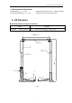
2.2 Main structure principles:
Lifting mechanism: Each column is installed
with a hydraulic cylinder, when hydraulic oil is
pressed from power pack into the lower
chamber of main cylinder, piston rod moves
upwards to drive the upward movement of
carriage through leaf chain.
Load supporting mechanism
:
When vehicle
drives into the working area, adjust the angle
and telescopic length of arms to make lifting
pads at an effective load supporting position
that contact with vehicle, and then adjust the
lower screw’s height of lifting pad to make it
applicable for vehicles with different chassis.
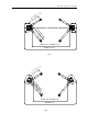
Balance mechanism
:
In order to keep machine
balanced during lifting and lowering, two
carriages are interconnected and forced to
move synchronously by two wire ropes. If the
right and left carriages and arms are not at the
same level, adjust the end nut of wire rope and
pull wire ropes tight to make arms leveled.
Manual safety locking mechanism: the safety
locking plates are installed on the two
carriages and the toothed bar plate is welded
on the internal wall of the column. During the
lifting of the carriage, the safety locking plate
goes up against on the toothed bar plate under
the tension of spring. When the carriage stops,
the safety locking plate opens and then is
engaged in the toothed bar slot to ensure the
carriage will not go down; when the lowering
operation is required, just raise the carriage
upward a little to loosen the safety locking
plate from the toothed bar slot, and then
manually pull the steel wire rope to let sliding
plate lift up the safety locking plate so that the
safety locking is released, the carriage can be
lowered down. Because the manual safety
locking device are installed on the two
carriages, double safety protection is provided;
therefore, to disengage the safety locking, the
steel rope on the two carriages shall be
respectively pulled. To prevent the vehicle
from slipping off, the swing arm assembly
employs positioning mechanism, makes the
swing arm capable of automatic locking during
operation.
Safety lock scope: Safety lock mechanism is
effective when the front end of carriage is
between 450mm and 1850mm high above the
ground.
3 Operation Descriptions
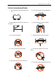
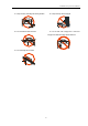
3.1 Precautions for vehicle repair
work
Different vehicles have different center of gravity
positions. First understand the position of center
of gravity, and when the vehicle enters into the
lift, make its center of gravity close to the plane
formed by two columns. Adjust the swing arm,
and make the lifting pad support onto the lifting
point of the vehicle.
For vehicle lift with top beam, pay attention to
the car roof position observation in order to
avoid accident during lifting.
Carefully read the warning symbol.
The hydraulic valves have been adjusted before
ex-factory, and the user can’t make
self-adjustment, otherwise it will be responsible
for all the consequences generated.
Based on the production, some specifications in
the instruction manual are subject to change
without notice.
3.2 Preparation before Operation
Lubricate contact surface of the carriage with
general-purpose lithium grease
(
GB7324-87
)
.
All sliding surface should be coated evenly from
the top to bottom.
Fill hydraulic oil N32 or N46 to the oil reservoir of
the power unit.
3.3 Inspection before operation
Check to see if the motor power is installed properly.
Check to see if all the connection bolts are fastened.
Note: Don’t operate the lift with damaged
cables or damaged and missing part, until it is
inspected and repaired by the professionals.
3.4 Lifting the Vehicle
Keep work area clean; don’t operate the lift in
cluttered work area.
Lower the carriage to the lowest position.
Reduce the swing arm to the minimum length.
Swing the arm along the route of the vehicle.
Move the vehicle to the location between the two
columns
Swing the arm and put the lifting pad below the
recommended lifting point, and adjust the height
of lifting pad to touch lifting point of vehicle
Press the UP button on the electric control box,
slowly lift the vehicle to ensure the load balance,
and then raise the lift to the required height.
Release the UP button.
Push the lowering handle to engage the safety
lock of carriage. At this time, the vehicle can be
repaired.