LAUREATE SERIES 2 COUNTER / TIMER / SERIAL INPUT METER OWNERS MANUAL Now with Ethernet LAUREL Electronics Inc. 3183-G Airway Ave, Costa Mesa, CA, 92626, USA Tel: (714) 434-6131 • Fax: (714) 434-3766 • Website: www.laurels.
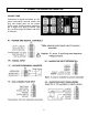
1. ORDERING GUIDE Configure a model number in this format: L50200FR L.........Counter / timer / serial input meter Extended counter Includes screw terminal connectors. Above plus rate and total simultaneously, custom curve linearization, arithmetic funcProcessors & Display Color tions (A*B, A/B, A+B, A-B, A/B-1), phase 5 ......................................Basic, Green LED angle, duty cycle, up/down counting, batch 6 ......................................... Basic, Red LED control. 7 .....................
2. TABLE OF CONTENTS 1. ORDERING GUIDE ..................................................................................................... 2 2. 3. 4. 5. TABLE OF CONTENTS............................................................................................... PRODUCT INTRODUCTION....................................................................................... RECEIVING & UNPACKING ....................................................................................... SAFETY CONSIDERATIONS.
3. PRODUCT INTRODUCTION Our counters are a versatile, cost effective solution to a wide range of monitoring and control applications including frequency, rate, total, period, time, phase, position, and flow. Setup can be via front panel pushbuttons or a PC. Selective lockout of front panel keys protects against accidental or unauthorized setup changes and simplifies meter use.
4. RECEIVING & UPACKING Your meter was carefully tested and inspected prior to shipment. Should the meter be damaged in shipment, notify the freight carrier immediately. In the event the meter is not configured as ordered or the unit is inoperable, return it to the place of purchase for repair or replacement. Please include a detailed description of the problem. 5.
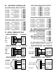
. CONNECTOR WIRING INFORMATION CONNECTORS Connectors for signal and power are U/L rated screw-clamp terminal blocks that plug into mating jacks on the printed circuit board. Communication connectors are a single RJ11 plug for RS232, dual RJ11 or RJ45 plugs for RS485, and RJ45 for Ethernet.
P3 - SERIAL OMMUNICATIONS RS232 INTERFACE N/C ISO GND RX TX RTS N/C 6 5 4 3 2 1 Computer GND TX RX RTS P4 – DUAL ANALOG OUTPUT, provides two unipolar connections at pins 1,2,3 and 4,5,6 RS485 INTERFACE - FULL DUPLEX ISO GND BRX ARX ATX BTX ISO GND RS485 INTERFACE - HALF DUPLEX ISO GND GND BTX ATX ARX BRX GND 6 5 4 3 2 1 ATX / ARX BTX / BRX ISO GND RS485-MODBUS - FULL DUPLEX (A') RXD0 (B') RXD1 + (B) TXD1 * (A) TXD0 ISO GND 1 2 3 4 5 6 7 8 GND 6 5 4 3 2 1 ATX / ARX BTX / BRX GND RS485-MODBUS -
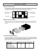
7. MECHANICAL ASSEMBLY REMOVING THE REAR PANEL First remove any connectors. Use one hand to press in the two sides of the rear of the case, and the other hand to press down the two protruding tab releases at the top of the rear panel (see figure below). This will unhook the rear panel from the case.
Note: Corresponding main board and option board connectors have the same number of electrical lines. When an option board is correctly installed, the top and bottom edges of the main board and option board are aligned. REASSEMBLING YOUR METER Slide the electronics assembly into the case until the display board is seated flush against the front overlay. Insert the bottom tabs of the rear panel into the case, then carefully align the board connectors with the openings in the rear panel.
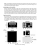
8. FRONT PANEL SETUP KEYS Counter Front Panel There are four front panel keys, which change function for the Run Mode and Menu Mode, effectively becoming eight keys. The keys are labeled with alphanumeric captions (MENU, PEAK, RESET, ALARMS) for the Run Mode and with symbols ( right arrow, right left arrow) for the Menu Mode.
RESET Key. Pressing RESET with PEAK resets peak and valley values. Pressing RESET with ALARMS resets latched alarms. Pressing RESET with MENU performs a meter reset (same as power on). Pressing and releasing RESET without pressing another key changes the displayed item if the mode has multiple items. For Item 1, the V LED is out. For Item 2, the V LED is on. For Item 3, the V LED is flashing. ALARMS Key. Pressing ALARMS once displays the setpoint for Alarm 1.
9. ENABLING & LOCKING OUT MENU ITEMS For security reasons and ease of operation, any and all menu items may be disabled or "locked out" so that they are no longer directly accessible from the front panel. Each function to be enabled is set to "0" and each function to be disabled is set to "1" in menu items Loc 1-4. These menu items can in turn be locked out by installing an internal hardware jumper. With the jumper installed, the operator only has access to enabled menu items.
10. DUAL CHANNEL PULSE OR AC INPUT SIGNAL CONDITIONER The dual channel signal conditioner board is used for the frequency, rate, period, timing, batch control, phase and duty cycle meter functions. The board needs to be configured via jumpers for the input signal type and level. It is recognized by the meter software, which will bring up the applicable menu items.
Common Jumper Settings Input Type Logic levels NPN open collector PNP open collector Contact closures Line frequency Turbine flow meter Vmax A0 & B0 A1 & B1 A2 & B2 A3 & B3 A4 & B4 250V NA NA NA 250V 250V b b a or b b b a b a - a a a b a - b b b a, c a, c b OVERVIEW OF OPERATING MODES RATE & FREQUENCY MODES Frequency in Hz is determined by timing an integral number of pulses over a user-specified gate time from 0 to 199.99 sec and taking the inverse of average period.
DISPLAY 0-50.00 RATE FROM 1-10 kHz INPUT, COORDINATES OF 2 POINTS METHOD Application: Display 0-50.00 (with two decimal places) for 1-10 kHz input. Use coordinates of 2 points scaling method. Solution: Set Input to “Rate A Only.” Select “coordinates of 2 points” scaling method under Setup. This is easier than scale and offset. Set DecPt1 to two places. Then enter the low input and desired low reading, and high input and desired high reading, as shown. DISPLAY RATE IN GPM FROM 36.
• RATE A, TOTAL B (A_btot) (Extended counter) displays Rate for Channel A as Item #1 and Total for Channel B as Item #2. • RATES A+B, A-B, AxB, A/B, A/B-1 (Extended counter) display arithmetic combinations of Rates A and B as Item #1, Rate A as Item #2, and Rate B as Item #3. With rates A and B scaled to produce a ratio close to 1 and an offset of -1, the special combination A/B-1, called “Draw,” can display percentage changes, such as elongation of material as it passes between rollers.
DISPLAY TOTAL VOLUME BY ADDING TWO TURBINE FLOW METER CHANNELS Application: Display total liquid volume in gallons to two decimal places from 2 pipes dispensing liquids into the same tank. Flow meter A is calibrated to 36.67 pulses/gallon, flow meter B to 58.12 pulses/gallon. Solution: Arithmetic operations require the Extended counter. Apply flow meter output A output to Channel A, flow meter output B to Channel B. Set Input to “Total A+B.” Set Gate Time to 0.01 sec for fast display updates.
• TOTAL A B INHIBIT (A_bInH) (Extended counter) displays Total A as Item #1, where counting may be inhibited by a control input on Channel B. If the menu item SLOPE is set to 0 for Channel B (digit 6), a low input level on B allows counting, and a high input level inhibits counting. If the SLOPE for Channel B is set to 1, the opposite occurs. The maximum frequency on A that can be counted is 1 MHz. Overflows are displayed as #2. (See Total A only) BATCH CONTROL MODE (_bAtCH) BATCH CONTROL WITH A 36.
• In batch control mode with external resets, pushing the RESET key initiates cycling. Grounding an external Gate input for a minimum of 3.33 ms then starts each new fill cycle by energizing Relay #1 and resetting the Batch Total. Gate time is not used. Three values are tracked and can be separately displayed by pressing the RESET key: Item #1, the Batch Total; Item #2, the Grand Total of all batches or Number of Batches (selectable during setup); and Item #3, the Fill Rate.
STOPWATCH TIMING, CLOSING TIME OF A RELAY TO 0.001 MSEC RESOLUTION Application: Measure the closing time of a relay in msec to 0.001 msec resolution. Solution: To close the relay, apply the same positive voltage to the relay coil and to meter Channel A. Wire the relay so that 0V is applied across Channel B when the contacts are closed. Set Input to “Stopwatch A to B.” Select a positive trigger slope for A and a negative trigger slope for B. Under Config, set Display Mode to sec. Set Gate Time to 0.01 sec.
• INVERSE STOPWATCH TIME A TO A & A TO B (__1/AA & 1/AB) (Extended counter) Takes the inverse of stopwatch time for a reading in /second. For example, if the travel time for an object to travel from point A to point B is 5 seconds, the inverse stopwatch time interval would be 0.2/sec. For the speed of that object, simply multiply by a scale factor equal to the distance separating the two points, such as 7 (inches). Speed would then be displayed as 7 x 0.2 = 1.4 (inches/sec).
POWER FACTOR MODE (PHASE) (Extended counter) The power factor of an AC power system is the ratio of real power in watts (W) divided by apparent power in volt-amperes (VA). For sinusoidal signals differing by a phase angle θ, power factor will be cos(θ), which is how the meter computes power factor. Power Factor readings can range from 1.000 to 0.000 with three decimal places and an accuracy of 0.1% for sinusoidal signals at 50/60 Hz AC line frequency. Maximum frequency is 1 kHz.
Example of Using OCV of 0 to 2.000 for setting Analog Output 4 mA output is desired for Power Factor of -0.4 (OCV = 0.400). 20 mA output is desired for Power Factor of +0.4 (OCV = 2.000 - 0.4 = 1.600). Set up as follows: deC.Pt to 111.111, AnSEt to 21, An_Lo to +0.400 (4 mA point), An_Hi to +1.600 (20 mA point), dEC.Pt as desired to 111.111, 1111.11 or 11111.1 Example of Using OCV of 0 to 2.000 for setting the Alarm Setpoints It is desired to operate Relay1 when the Power Factor falls outside of ±0.
SETUP OF COUNTERS WITH DUAL CHANNEL PULSE SIGNAL CONDITIONER key does not work, see Section 9 “Enabling & Locking Out Menu Items.” If the MENU Menus are dynamic. Menu items will only appear if appropriate for previously made menu selections. For example, Batch menu items will only appear if “Batch” was selected under “Rate.” Extended counter items will only appear if “Extended” was selected under “Config.” Basic __rAtE Rate modes Press Value Select Key A__b__ Rate for Channel A (Item #1).
_InPut _totAL. (continued) Total modes Press Value Select Key Basic Press Digit Select Key A__b__ Total for Channel A (Item #1). Total for Channel B (Item #2). A_OnLy Total for Channel A only (Item #1). A-b_Ud. Running total (Item #1) of counts on Channel A minus counts on Channel B. _burSt. Count of bursts (Item #1). Burst frequency (Item #2). Extended meter only b_ArAt. Total for Channel B (Item #1).
_InPut PHASE (continued) Phase angle modes duty_C Duty cycle mode SEtuP Setup Press Value Select Key Extended Press Digit Select Key Ext. Press Menu _0-360. Span from 0° to 360°. Select for phase angles centered around 180° (Item #1). _-180+. Span from -180° to +180°. Select for phase angles centered around 0° (Item #1). A_to_b On or Off period of square waves as a percentage of total period (Item #1). _00000 Stored totals 0 Zero totals at power-on. 1 Restore totals at power-on.
Press Menu ConFiG Configuration dSPyno Display # Press Digit Select Key Press Value Select Key __0000 Display mode 0 1 2 3 4 5 6 7 8 9 A B C Normal, overload to exponential format Normal, overload to 999999 1 right-hand dummy zero 2 right-hand dummy zeros Time display in seconds Time display in HH.MM.
Press Menu Press Digit Select Key bAtCH _00000 (continued) Definition of Item #2 FiLtEr Filtering .SLOPE Triggering Press Value Select Key 0 Make Item #2 the Grand Total of all batches. 1 Make Item #2 the Total Number of batches. _00000 Action after Meter Reset 0 Display “rEAdy.” RESET key starts batching. 1 Start batching upon Meter Reset. _00000 Filter type 0 Adaptive moving average filter. Restarts filter for high actual changes in signal. 1 Conventional moving average filter without reset.
Press Menu Press Digit Select Key Press Value Select Key Coordinates of 2 points scaling method if selected under SEtuP .Lo_In1. Low signal input 1. 000000 000000 000000 000000 000000 000000 Select digit to flash. Select -9 thru 9 for flashing first digit and 0 thru 9 for other flashing digits. Move decimal point location when flashing. Lo_ rd1 Reading at Lo In1. 000000 000000 000000 000000 000000 000000 Select digit to flash.
Scale multiplier for combinations of two channels (e.g., AxB, A/B) if selected under _InPut rESoLn. Resolution Flashing 6-digit number in decade steps from 0.00001 to 100000 Press to select. This is a multiplier R to avoid overflow or underflow of arithmetic combinations of Channels A and B. Quartz crystal time base calibration _CALib Time base calibration. Do not change. See Calibration section of manual. Option dependent menu items SourcE AL SEt.
11. PROCESS RECEIVER & TOTALIZER SIGNAL CONDITIONER This signal conditioner board converts 0-1 mA, 4-20 mA or 0-10 V analog process signals to a frequency signal, which is then read by the counter main board and processed mathematically for display of rate, total (time x rate), time based on rate, or batch control. The board needs to be configured via jumpers for the input signal range. The meter software recognizes the board and brings up the applicable menu items for it.
noise filtering. Moving average filtering is also available. Square root extraction is selectable for use with differential pressure flow transducers. Custom curve linearization is available with the Extended counter. RATE & TOTAL MODE (Basic Counter) TOTAL FROM A 4-20 mA OUTPUT FLOW METER Application: Display Total from a 4-20 mA flow Solution: Set Input to “VF420 A A Total,” meter where 4 mA = 0 and 20 mA = 5.820 GPM. which displays Rate as Item #1 & Total as Item #2.
• In batch control mode with “external gate”, the meter waits a the end of every cycle until an external gate input is grounded for a minimum of 3.33 ms. This starts a new fill cycle by energizing Relay #1 and resetting the Batch Total. Gate time is not used. Three values are tracked and can be separately displayed by pressing the RESET key: Item #1, the Batch Total; Item #2, the Grand Total of all batches or Number of Batches (selectable during setup); and Item #3, the Fill Rate.
KEYSTROKES FOR SETUP key does not work, see Section 9 “Enabling & Locking Out Menu Items.” If the MENU Menus are dynamic. Menu items will only appear if appropriate for previously made menu selections. For example, Batch menu items will only appear if “Batch” was selected under “Rate.” Extended counter items will only appear if “Extended” was selected under “Config.
Press Menu Press Digit Select Key Press Value Select Key __0000 Display mode 0 1 2 3 4 5 6 7 8 9 A B C Normal, overload to exponential format Normal, overload to 999999 1 right-hand dummy zero 2 right-hand dummy zeros Time display in seconds Time display in HH.MM.
Press Menu Press Digit Select Key bAtCH _00000 & _00000 Batch setup _00000 Batch triggering FiLtEr Filtering Press Value Select Key 0 Not used with VF Batch. Set to 0. 0 Use gate time* as delay between batches. 1 Use External Input B to start each new batch. _00000 Definition of Item #2 0 Make Item #2 the Grand Total of all batches. 1 Make Item #2 the Total Number of batches. _00000 Action after Meter Reset 0 Display “rEAdy.” RESET key starts batching. 1 Start batching upon Meter Reset.
Press Menu Press Digit Select Key Press Value Select Key Coordinates of 2 points scaling method if selected under SEtuP .Lo_In1. Low signal input 1. 000000 000000 000000 000000 000000 000000 Select digit to flash. Select -9 thru 9 for flashing first digit and 0 thru 9 for other flashing digits. Move decimal point location when flashing. Lo_ rd1 Reading at Lo In1. 000000 000000 000000 000000 000000 000000 Select digit to flash.
12. QUADRATURE SIGNAL CONDITIONER Our quadrature signal conditioner board can be used for quadrature position (with Basic or Extended main board) or for quadrature rate (with Extended main board). Two quadrature signals, which are 90º out of phase, are applied to the Channel A and B inputs. Their phase relationship determines whether the count is up (+) or down (-). A zero index signal may be applied to Channel Z as a position reference.
Jumper Settings Note: Letters indicate jumper position. Jumpers are installed on pins adjacent to letters.
PRINCIPLE OF OPERATION The quadrature decoder board generates up (+) and down (-) counts that are arithmetically totalized on the main counter board and are then displayed. The decoder board has input circuitry that may be jumpered for single-ended input signals or balanced line driver signals. It accepts normal A & B quadrature signals and, if present, a zero index signal.
The zero index channel has the same digital filtering as the A & B channels. It contains a Polarity jumper that allows selection of either a positive or negative zero index signal. It also contains two Control inputs, C1 and C2 that control the ANDing of the zero index signal with the Channel A and Channel B signals. See “Zero Index Setup” below. The Item indicator light (center right) may be used to determine the location of the Zero Index.
ZERO INDEX SETUP The relationship between the zero index correction signal and the Channel A & B signals varies by encoder model and by manufacturer. To accommodate this variation, the Quadrature board has control jumpers and selectable outputs that provide ANDing of the zero index signal with all possible combinations of the Channel A & B signals. Consider a typical encoder model that produces the waveforms shown below. Assume that X4 counting is selected.
By ANDing the zero index signal with the A & B channels, there is no regional discrepancy between counting up and counting down. There are 2 control signals, C1 and C2, and 3 outputs, ZI, ZIX and ZIY. These may be jumpered to provide 8 selections of ANDed signals or the zero index signal without ANDing.
8. Rotate the optical encoder past the zero index point to set the internal correction. 9. Return to the desired zero mechanical position and verify a zero reading. This completes the procedure. If the encoder is rotated back to mechanical zero, it should read zero.
WAVESHAPE EXAMPLES BY ENCODER MANUFACTURER A Channel B Channel Zero Index Allen Bradley: current sink, open collector & line driver, CCW rotation A Channel B Channel Zero Index Allen Bradley: current source, CCW rotation. A Channel B Channel Zero Index Zero Index (gated) BEI: Models H25, L25, E25, MOD5500, MOD5600,CCW rotation . A Channel B Channel Zero Index BEI: Models MX-51, MX-21,CCW rotation . A Channel B Channel Zero Index BEI: Models E20, E11, E15, CMX216, MOD900, CW rotation . 45 .
A Channel B Channel Zero Index Bourns: EN Series. A Channel B Channel Zero Index 90-270 deg Computer Optical Products Models CP-350, CP-360, CP-370, CP-850, CP870,CCW rotation. A Channel B Channel Zero Index Encoder Prod: Models H25, L25, E25, MOD5500, MOD5600,CCW rotation . A Channel B Channel Grayhill & Oak-Grigsby: CW rotation. No Zero Index. QUADRATURE RATE Rate and direction may also be displayed using an extended version of the counter.
PROGRAMMING EXAMPLE FOR QUADRATURE TOTAL: DISPLAY DISTANCE TO 0.001 FT FROM A 1024 PULSE/REV QUADRATURE ENCODER Application: Display distance in feet with 3 decimal points using a 1024 pulse/revolution quadrature encoder tied to a roller with 1.782 ft circumference. Solution: Set Input to “Quadrature Total.” Set Gate Time to 0.01 sec for fast display updates. Set DecPt1 to 3 places. Under Setup, select coordinates of 2 points scaling method. Set Hi In1 to 1024.0 (pulses) and the desired Hi Rd1 to 1.
E 1 = Display Blank, 2 = External Gate* F 1 = Display Item #2, 2 = Display Item #3 With 1 and 2 at 5V or open, Display Item #1. ------------------------------------------------------------------* 1 & 2 both at 0V = Meter Reset (can restore totals). ** 1 & 2 both at 0V for selections 5, 7, 8, D = Function Reset* (erases all totals). __0000 Display mode 0 Normal, overload to exponential format 1 Normal, overload to 999999 Normally select 1, required for Preset function.
Press Menu Press Digit Select Key Press Value Select Key Coordinates of 2 points scaling method if selected under SEtuP .Lo_In1. Low signal input 1. 000000 000000 000000 000000 000000 000000 Select digit to flash. Select -9 thru 9 for flashing first digit and 0 thru 9 for other flashing digits. Move decimal point location when flashing. Lo_ rd1 Reading at Lo In1. 000000 000000 000000 000000 000000 000000 Select digit to flash.
PROGRAMMING EXAMPLE FOR QUADRATURE RATE: DISPLAY RATE TO 0.001 FT/SEC FROM A 1024 PULSE/REV QUADRATURE ENCODER Application: Display rate in feet/sec with 3 decimal points using a 1024 pulse/revolution quadrature encoder tied to a roller with 1.782 ft circumference. Have 4 display updates per second. Solution: Set Input to “Quadrature Rate.” Set Gate Time to .22 sec so that the display update rate becomes .22 sec +30 ms +1 period. Set Time-out to 1 sec, so that pulse rates under 1 Hz are displayed as 0.
KEYSTROKES FOR SETUP OF QUADRATURE RATE If the MENU Press Menu key does not work, see Section 9 “Enabling & Locking Out Menu Items.” Press Digit Select Key Press Value Select Key _InPut Input _quAdr Basic meter _totAL Quadrature total Quadrature Extended _rAtE_ Quadrature rate SEtuP Setup _00000 Not applicable 0 Set to zero. _00000 Leading zeros 0 Blank leading zeros. 1 Display leading zeros.
Press Menu dSPyno Display # Press Digit Select Key Press Value Select Key ____01 PEAK key action 0 Display Peak 1 Display Valley 2 Peak (1st push), Valley (2nd push) ____01 Item to display after Meter Reset 1 Item #1* (Quadrature Rate = Rate A - Rate B) 2 Item #2* (Rate A) 3 Item #3* (Rate B) GAtE_t Gate time* _000.00 _000.00 _000.00 Select 0 thru 9 for flashing digit to set gate time* in seconds. Decimal point location is fixed for 10 ms _000.00 _000.00 resolution. Select digit to flash. .ti_Out.
Coordinates of 2 points scaling method if selected under SEtuP .Lo_In1. Low signal input 1. 000000 000000 000000 000000 000000 000000 Select digit to flash. Select -9 thru 9 for flashing first digit and 0 thru 9 for other flashing digits. Move decimal point location when flashing. Lo_ rd1 Reading at Lo In1. 000000 000000 000000 000000 000000 000000 Select digit to flash. Select -9 thru 9 for flashing first digit and 0 thru 9 for other flashing digits. Decimal point is fixed by dEC.Pt1. .Hi_In1.
13. SERIAL INPUT METER / REMOTE DISPLAY OPERATION With a Basic counter main board and a serial interface board, the counter can operate as a 6-digit serial input meter (or remote display) to display serial data received from a computer or PLC, or act as a slave display to another meter, counter or timer with a serial output. A signal conditioner board is not required, but will not interfere with remote display operation if installed.
Additional programmable features of the serial input meter are detailed in the “Command Mode for Remote Display Operation of Counter / Timer” and “Data Formats” sections of the Custom ASCII Protocol Serial Communications Manual. In particular, Mode 12 (hex C), which is invoked by setting the first digit under ConFIG to C, allows extraction of data from an ASCII string that contains multiple data values or non-numeric characters. This mode can accommodate selected Start and Stop characters.
14. DUAL & QUAD RELAY OUTPUT OPTIONS An optional relay board may be installed in the meter main board at plug position P2, adjacent to the power supply board. Four board versions are available: 2 or 4 relays, contact or solid state. Once installed, the relay board is recognized by the meter software or PC-based Instrument Setup software, which will bring up the appropriate menu items for the type of board. These menu items will not be brought up if a relay board is not detected.
KEYSTROKES FOR SETUP key does not work, see Section 9 “Enabling & Locking Out Menu Items.” If the MENU Press Menu Press Digit Select Key Press Value Select Key SourcE 0000 Source to com- Setpoint 1 compared to: pare to setpoint 0000 Setpoint 2 compared to: 1. Filtered item 1 Item #1 2 Item #2 3 Item #3 1. Filtered item 1 Item #1 2 Item #2 3 Item #3 0000 Setpoint 3 compared to: 1. Filtered item 1 Item #1 2 Item #2 3 Item #3 0000 Setpoint 4 compared to: 1.
Press Menu Press Digit Select Key Press Value Select Key 0 1 2 3 Relay 3 active on Relay 3 active off Relay 3 active on Relay 3 active off Relay 4 active on Relay 4 active on Relay 4 active off Relay 4 active off 00000 Alarm latching or nonlatching (auto reset). (see Glossary) 0 1 2 3 AL3 non-latching AL3 latching AL3 non-latching AL3 latching AL4 non-latching AL4 non-latching AL4 latching AL4 latching 00000 Alarm operates at and above setpoint (active high) or at and below setpoint (active low).
15. SINGLE & DUAL ANALOG OUTPUT OPTIONS Two versions of an analog board may be installed in the meter at rear panel jack position J4, adjacent to the signal conditioner board. Once installed, this board is recognized by the meter, which will bring up the appropriate menu items for it. These will not be brought up if an analog output board is not installed.
KEYSTROKES FOR SETUP OF DUAL ANALOG OUTPUT BOARD If the MENU key does not work, see Section 9 “Enabling & Locking Out Menu Items.
16. SERIAL COMMUNICATIONS OPTIONS A serial communications board may be connected to the meter main board at plug position P13 (middle position). Available boards are RS232, RS485 (with dual RJ11 connectors), RS485 Modbus (with dual RJ45 connectors), USB, USB-to-RS485 converter, Ethernet, and Ethernet-to-RS485 converter. The dual connectors of RS485 boards are wired in parallel to allow daisy chaining of addressable meters without use of a hub.
Basic Ethernet Board No jumpers needed. RS232 Board e - Normal operation. f - Slave display to RS232 from another meter. g - Pull-up resistor on RTS line. Note: Board is shipped with jumpers e and g installed RS485 Board, Full Duplex Operation b & d - Installed on last meter in long cable run. RS485 Board, Half Duplex a & c - Installed for half duplex operation. d - Installed on last meter in line with long cable runs. Note: Board is shipped with no jumpers installed.
SERIAL CONNECTION EXAMPLES 63
KEYSTROKES FOR SETUP If the MENU key does not work, see Section 9 “Enabling & Locking Out Menu Items.” Press Menu Key .Ser 1. Serial Setup 1. Press until Ser 1 is displayed. Fixed Parameters No parity 8 data bits 1 stop bit .Ser 2. Serial Setup 2 Press Digit Select Key Press Value Select Key ___000 Output filtering 0 Send unfiltered signal 1 Send filtered signal ___000U Baud rate 0 1 2 3 300 baud 600 baud 1200 baud 2400 baud ___000U Digital output rate. rr = reading rate.
Press Menu Key .Ser 3. Serial Setup 3 Ser 4. Serial Setup 4 _Addr Modbus Address Press Digit Select Key Press Value Select Key _00000U Half or full duplex 0 Full duplex _00000U Recognition characters, start & stop characters. Special characters have to be download via Instrument Setup software. 0 * (asterisk) is recognition character. No start & stop characters. 1 Custom recognition character. No start & stop characters. 2 * (asterisk) is recognition character. Special start & stop characters.
17. EXCITATION OUTPUT & POWER SUPPLY Three isolated transducer excitation output levels are available from the power supply board. These are selectable via jumpers b, c, d, e, f in the upper right of the board, as illustrated. In addition, the board provides three jumper positions for special features. The same jumper locations apply to the universal power supply (85-264 Vac or 90-300 Vdc) and to the low voltage power supply (12-32 Vac or 10-48 Vdc). 1. Letters indicate jumper position.
18. INSTRUMENT SETUP VIA PC Instrument Setup software is a PC program which is much easier to learn than front panel programming. It is of benefit whether or not the meter is connected to a PC. With the meter connected to a PC, it allows uploading, editing and downloading of setup data, execution of commands under computer control, listing, plotting and graphing of data, and computer prompted calibration.
SETUP OF CONNECTED METER A setup file can be retrieved from the meter (Counter => Get Setup), be edited (View => Setup), be saved to disk (File => Save Setup), be retrieved from disk (File => Open Setup), and be downloaded into one or multiple meters (Counter => Put Setup). Downloading of setup files from a PC can be a major time saving when multiple counters have to be set up in the same way.
• The Readings pull-down menu provides three formats to display meter data on the PC monitor. Use the Pause and Continue buttons to control the timing of data collection, then press Print for a hardcopy record on your PC printer. - List presents the latest readings in a 20-row by 10-column table. Press Pause at any time to freeze the display. This is one method to capture peak readings. - Plot generates a plot of readings vs. time in seconds.
19. CUSTOM CURVE LINEARIZATION Curve.exe is a DOS-based, executable PC program used to set up an Extended meter so that the readings have a user-defined, non-linear relationship with the input signal. For example, it allows a meter to correct for non-linearity of transducers, or to display volume from pressure at the bottom of an irregularly shaped tank. The linearizing parameters are downloaded into non-volatile memory of the meter.
4) Equation entry mode, where the coefficients of a polynomial Y = K1X^P1 + K2X^P2 + K3*X^P3 + … are entered. Up to 20 terms are allowed. And offset can be built into X. REQUIRED USER INPUTS • Select CTR • You will be asked to supply the following: LOW X-COORDINATE VALUE > LOW INPUT MEASUREMENT VALUE > HIGH X-COORDINATE VALUE > HIGH INPUT MEASUREMENT VALUE > This informs the computer of your signal conditioner jumper settings. Enter 0 and 0 for the two LOW values.
21. SPECIFICATIONS DISPLAY Type ................................................6 LED digits, 7-segment, 14.2mm, plus 4 LED indicators Digit Color ...........................................................................................................Red or green Display Range ......................................................................................... -999999 to +999999 CONVERSION (FREQUENCY INPUT) Conversion Technique ........................................................................
Conversion Time for Rate .......................................... Gate time + 30 ms + 0-2 signal periods Time Before Zero Output for Rate ................................................0 to 199.99 sec (selectable) Zero Wait Time for Rate ...............................................................0 to 199.99 sec (selectable) Output & Display Update Rate ......................................................... Same as conversion rate Time Base Accuracy for Rate.........................................
ANALOG OUTPUT OPTION Power to Analog Output Option...................................................................Powered by meter Output Levels, Single Analog Output Option.............. 0-20 mA, 4-20 mA, 0-10V, -10 to +10V Output Levels, Dual Analog Output Option ..................................... 0-20 mA, 4-20 mA, 0-10V Voltage Compliance, 0-20 mA Output .................................................. 12V (0-600 Ohm load) Current Compliance, 0-10V Output .........................................
22. GLOSSARY OF TERMS Adaptive filter threshold A threshold which causes an adaptive moving average filter to be reset to the latest reading when the accumulated difference between individual readings and the filtered reading exceeds that threshold. Adaptive moving average filtering allows a meter to respond rapidly to actual changes in signal while filtering out normal noise. The accumulated difference is also reset to zero when the latest reading has a different polarity than the filtered reading.
Custom ASCII protocol A simplified, short protocol for use with panel meters, counters and timers. It allows 31 digital addresses. Not an industry-standard protocol, like the more complex Modbus protocol, which is also offered with these instruments. Custom curve A user-specified nonlinear relationship between the input signal and displayed reading. Custom curve linearization is available with the Extended counter.
produces a more stable reading as more cycles are averaged, but slows down the update rate. At very low frequencies, the update rate of the meter is controlled by the period. In totalizing mode, the gate is always open, but the gate time setting still determines the update rate of the meter. See also Timeout or Time before zero output. Hysteresis, Band A band in counts which controls relay action symmetrically around a setpoint.
more dynamic range with no loss of resolution than could be achieved with a 6digit scale factor only. Offset A constant adder to the displayed reading. This may be any value from -999,999 to 999,99. The offset may be used as a preset in the totalize mode, where the total can be counted down from the preset to zero. Peak display The maximum (or most positive) reading since that value was last reset. Reset can be via the meter front panel, an external input, or a software command.
RS485 half duplex Serial communications implemented with two wires, allowing data transmission in both directions, but not simultaneously. RS485 full duplex Serial communications implemented with four wires, allowing data transmission in two directions simultaneously. Run Mode The normal operating mode of the meter, where readings are taken, as opposed to the menu mode. Scale factor A constant multiplier used to go from a raw reading in pulses per second or total pulses to a reading in engineering units.
23. WARRANTY Laurel Electronics Inc. warrants its products against defects in materials or workmanship for a period of one year from the date of purchase. In the event of a defect during the warranty period, the unit should be returned, freight prepaid (and all duties and taxes) by the Buyer, to the authorized Laurel distributor where the unit was purchased. The distributor, at its option, will repair or replace the defective unit.