LAUREATE SERIES 2 DIGITAL PANEL METER OWNERS MANUAL Now with Ethernet LAUREL Electronics Inc. 3183-G Airway Ave, Costa Mesa, CA, 92626, USA Tel: (714) 434-6131 • Fax: (714) 434-3766 • Website: www.laurels.
1. ORDERING GUIDE Configure a model number in this format: L20201DCV1, CBL01 L…….Digital panel meter with screw terminal connectors. Display Color 1...............DPM with green LED 2.................. DPM with red LED 3..... Extended DPM, green LED 4........ Extended DPM, red LED Note: Extended adds rate of change & linearization of nonlinear inputs. Not applicable to thermocouple or RTD inputs. Power 0............................. 85-264 Vac 1.......... 10-48 Vdc or 12-32 Vac Setpoint Output 0............
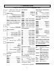
2. TABLE OF CONTENTS 1. 2. 3. ORDERING GUIDE ..................................................................................................... 2 TABLE OF CONTENTS............................................................................................... 3 PRODUCT INTRODUCTION....................................................................................... 4 4. 5. 6. 7. RECEIVING & UNPACKING .......................................................................................
3. PRODUCT INTRODUCTION Our digital panel meters are versatile, cost effective solutions to a wide variety of monitoring and control applications. Depending on the choice of signal conditioner, they are easily set up for an accurate display of temperature, pressure, flow, weight, voltage or current, all in appropriate engineering units and with zero and span adjustment when needed. Setup can be via front panel pushbuttons or the meter’s serial interface.
4. RECEIVING & UNPACKING Your meter was carefully tested and inspected prior to shipment. Should the meter be damaged in shipment, notify the freight carrier immediately. In the event the meter is not configured as ordered or the unit is inoperable, return it to the place of purchase for repair or replacement. Please include a detailed description of the problem. 5.
. CONNECTOR WIRING INFORMATION CONNECTORS Connectors for signal and power are UL-rated screw-clamp terminal blocks that plug into mating jacks on the printed circuit board. Communication connectors are a single RJ11 plug for RS232, dual RJ11 plugs for RS485, dual RJ45 plugs for RS485 Modbus, or USB. Note: Control inputs 1 & 2 of P1 are menu selectable. Warning: Hazardous voltages may be present on pins 4, 5 & 6 of P1 since digital ground is tied to pin 3 of P5 (-Signal Input).
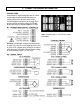
P3 - SERIAL COMMUNICATIONS RS232 INTERFACE N/C ISO GND RX TX RTS N/C 6 5 4 3 2 1 P4 - ANALOG OUTPUT Computer GND TX RX RTS RS485 INTERFACE - FULL DUPLEX ISO GND BRX ARX ATX BTX ISO GND GND BTX ATX ARX BRX GND 6 5 4 3 2 1 RS485 INTERFACE - HALF DUPLEX ISO GND ATX / ARX BTX / BRX ISO GND RS485-MODBUS - FULL DUPLEX (A') RXD0 (B') RXD1 + (B) TXD1 * (A) TXD0 ISO GND 1 2 3 4 5 6 7 8 GND 6 5 4 3 2 1 ATX / ARX BTX / BRX GND RS485-MODBUS - HALF DUPLEX TXD0 TXD1 RXD1 RXD0 (B) TX / RXD1 (A) TX / RXD0 G
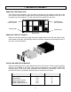
7. MECHANICAL ASSEMBLY REMOVING THE REAR PANEL First remove any connectors. Use one hand to press in the two sides of the rear of the case, and the other hand to press down the two protruding tab releases at the top of the rear panel (see figure below). This will unhook the rear panel from the case.
Note: Corresponding main board and option board connectors have the same number of electrical lines. When an option board is correctly installed, the top and bottom edges of the main board and option board are aligned. REASSEMBLING YOUR METER Slide the electronics assembly into the case until the display board is seated flush against the front overlay. Insert the bottom tabs of the rear panel into the case, and then carefully align the board connectors with the openings in the rear panel.
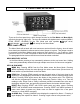
8. FRONT PANEL SETUP KEYS Meter Front Panel There are four front panel keys, which change function for the Run Mode and Menu Mode, effectively becoming eight keys. The keys are labeled with alphanumeric captions (MENU, PEAK, RESET, ALARMS) for the Run Mode and with symbols ( right arrow, right triangle, up triangle, left arrow) for the Menu Mode.
KEYS IN MENU MODE Right Arrow Key (MENU). Pressing steps the meter through all menu items that have been enabled and then back to the Run Mode. With the DC signal conditioner board and no option boards, available menu items are _InPut, SEtuP, ConFG, _FiLtr, dEc.Pt, SCALE, OFFst, Loc 1, Loc 2, Loc 3. If a change has been made to a menu item, that change is saved to non-volatile memory when the key is pressed next, and StoreE is displayed briefly. Right Triangle Key (Digit Select).
9. ENABLING & LOCKING OUT MENU ITEMS For security reasons and ease of meter operation, any and all menu items may be disabled or "locked out" so that they are no longer directly accessible from the front panel. Each function to be disabled is set to "1" in menu items Loc 1, Loc 2 or Loc 3, and each function to be enabled is set to "0." The top menu items Loc 1, Loc 2 and Loc 3 can in turn be locked out by installing an internal hardware jumper.
10. READING COORDINATES OF 2 POINTS SCALING METHOD When the reading coordinates of 2 points scaling method has been selected under SEtuP, the four menu items below will appear ahead of all other menu items when the MENU or key is first pressed from the run mode. This scaling method applies a straight line fit between two points, which are determined from actual transducer signals and the desired corresponding meter readings.
11. DC VOLTS, AMPS, PROCESS, STRAIN INPUT The DC Volts, Amps, Process and Strain meters utilize the DC signal conditioner board, which needs to be configured via jumpers for the desired voltage or current range. All signal ranges are factory calibrated with calibration factors stored in EEPROM. The meter software recognizes the board and will bring up the appropriate menu items for it; however, it does not recognize the jumper settings.
Board Revisions Q and R Voltage Ranges Jumpers FS Input E1 E2 E3 ±200.00 mV ±2.0000 V ±20.000 V ±200.00 V ±300V (UL) ±600V (not UL) A A B B B B f f h h g g b a b a a a Current Ranges E1 A h b Jumpers E3 FS Input E1 E2 E3 ±2.0000 mA ±20.000 mA ±200.00 mA ±5.000 A A A A A e, g d, g c, g a, b, g b b b b 1. 2. 3. 4. B a E2 g b a f c e d Letters indicate jumper position. Jumpers are installed on pins adjacent to letters. Use 5 mm (0.
KEYSTROKES FOR SETUP key does not work, see Section 9 “Enabling & Locking Out Menu Items.” If the MENU Press Menu Select Key _InPut Selection of signal input type & range SEtuP Meter Setup Press Digit Select Key Press Value Select Key _dC U DC Volts __0.2U __2.0U _20.0U 200.0U 600.0U 0.2, 2, 20, 200, 660V FS _dC A DC Amps __2.0a _20.0a _200.0a _5.0a 0.2, 20, 200 mA, 5A FS _rAtio Strain gauge & ratio __0.2U __2.0U _20.0U 0.2, 2, 20V FS. 00_00 Display selection with scale factor of 1.
Press Menu Select Key Press Digit Select Key ConFG 000_0 Meter Configuration Operation as a rate of change meter. Extended meter only. FiLtr Filtering dEc.Pt Dec. point selection Press Value Select Key 0 1 3 5 Not rate of change Rate x 0.1 2 Rate x 1 Rate x 10 4 Rate x 100 Rate x 1000 6 Rate x 10000 000_0 Operation of front panel PEAK button and rear connector for Peak or Valley Display 0 Peak Display. Also selects “Peak” in “Peak or Valley” at connector above. 1 Valley Display.
Press Menu Select Key Press Digit Select Key Press Value Select Key Scaling method “Scale and Offset” if selected under SEtuP SCALE Scale factor 0.0000 0.0000 0.0000 Select -9 thru 9 for flashing first digit, 0 thru 9 0.0000 0.0000 0.0000 for other flashing digits. Select decimal point location when decimal point is flashing. Select digit to flash. OFFst Offset value 0.0000 0.0000 0.0000 Select -9 thru 9 for flashing first digit, 0 thru 9 for other flashing digits. Decimal point 0.0000 0.
Option board dependent menu items ALSEt. ALS34 dEU1H dEU2H dEU1b dEU2b dEU3H DEU4H DEU3b DEU4b Menu items related to alarm setup These will only appear if a relay board is detected. If so, please see Section16. AnSEt. An Lo. An Hi.. Menu items related to analog output setup. These will only appear if an analog output board is detected. If so, see Section 17. SEr 1. SEr 2. SEr 3. SEr 4. _Addr Menu items related to serial communications. These will only appear if an RS232, RS485 or USB I/O board is detected.
12. LOAD CELL & MICROVOLT INPUT The Load Cell and Microvolt meters utilize the load cell signal conditioner board, which offers sensitivity to ±20 mV full scale and 4 or 6-wire load cell connection. This board needs to be configured via jumpers for the desired voltage range. All signal ranges are factory calibrated with calibration factors stored in EEPROM. The meter software recognizes the board and will bring up the appropriate menu items for it; however, it does not recognize the jumper settings.
KEYSTROKES FOR SETUP key does not work, see Section 9 “Enabling & Locking Out Menu Items.” If the MENU Press Menu Select Key Press Digit Select Key Press Value Select Key _InPut Selection of signal input type & range _Strn Strain or ratiometric _20.0____50.0_ _100.0 _250.0 _500.0 20, 50, 100, 250, 500 mV FS voltage _dC u U DC millivolts _20.0____50.0_ _100.0 _250.0 _500.
Press Menu Select Key Press Digit Select Key ConFG 000_0 Meter Configuration Operation as a rate of change meter. Extended meter only. FiLtr Filtering dEc.Pt Dec. point selection Press Value Select Key 0 1 2 3 4 5 6 Not rate of change Rate x 0.1 Rate x 1 Rate x 10 Rate x 100 Rate x 1000 Rate x 10000 000_0 Operation of front panel PEAK button and rear connector for Peak or Valley Display 0 Peak Display. Also selects “Peak” in “Peak or Valley” at connector above. 1 Valley Display.
Press Menu Select Key Press Digit Select Key Press Value Select Key Scaling method “Scale and Offset” if selected under SEtuP SCALE Scale factor 0.0000 0.0000 0.0000 Select -9 thru 9 for flashing first digit, 0 thru 9 0.0000 0.0000 0.0000 for other flashing digits. Select decimal point location when decimal point is flashing. Select digit to flash. OFFst Offset value 0.0000 0.0000 0.0000 Select -9 thru 9 for flashing first digit, 0 thru 9 for other flashing digits. Decimal point 0.0000 0.
Option board dependent menu items ALSEt. ALS34 dEU1H dEU2H dEU1b dEU2b dEU3H DEU4H DEU3b DEU4b Menu items related to alarm setup These will only appear if a relay board is detected. If so, please see Section16. AnSEt. An Lo. An Hi.. Menu items related to analog output setup. These will only appear if an analog output board is detected. If so, see Section 17. SEr 1. SEr 2. SEr 3. SEr 4. _Addr Menu items related to serial communications. These will only appear if an RS232, RS485 or USB I/O board is detected.
13. AC TRUE RMS VOLTS & AMPS INPUT AC voltage or current measurement utilizes the True RMS signal conditioner board which uses precision circuitry to compute the root-mean-square of complex waveforms from 10 Hz to 10 kHz. Accurate measurements are obtained with spikes up to 3 times the maximum of each range. The input can be AC coupled to read only the AC component, such as ripple on a power supply, or DC coupled to read AC plus DC.
can be set for direct readout in (milli)volts or (milli)amperes. Decimal point selection does not affect the counts. For example, a 20V input may be displayed as 20.000V or 20000 mV. The 5A range, designed for use with a 5A current transformer (CT), is scaled to produce 5000 counts with a scale factor of 1 and an offset of 0. Use with a specific CT will require the scale factor to be set. For example, for an 800A input, 5A output CT, set a scale factor of 1.6.
KEYSTROKES FOR SETUP key does not work, see Section 9 “Enabling & Locking Out Menu Items.” If the MENU Press Menu Select Key Press Digit Select Key Press Value Select Key _InPut Selection of signal input type & range _AC U AC Volts __0.2U __2.0U _20.0U 200.0U 600.0U 0.2, 2, 20, 200, 660V FS _AC A U AC Amps __2.0a _20.0a _200.0a _5.
Press Menu Select Key Press Digit Select Key ConFG 000_0 Meter Configuration Operation as a rate of change meter. Extended meter only. FiLtr Filtering dEc.Pt Dec. point selection Press Value Select Key 0 1 2 3 4 5 6 Not rate of change Rate x 0.1 Rate x 1 Rate x 10 Rate x 100 Rate x 1000 Rate x 10000 00 _ _0 Operation of front panel PEAK button and rear connector for Peak or Valley Display 0 Peak Display. Also selects “Peak” in “Peak or Valley” at connector above. 1 Valley Display.
Press Menu Select Key Press Digit Select Key Press Value Select Key Scaling method “Scale and Offset” if selected under SEtuP SCALE Scale factor 0.0000 0.0000 0.0000 Select -9 thru 9 for flashing first digit, 0 thru 9 0.0000 0.0000 0.0000 for other flashing digits. Select decimal point location when decimal point is flashing. Select digit to flash. OFFst Offset value 0.0000 0.0000 0.0000 Select -9 thru 9 for flashing first digit, 0 thru 9 for other flashing digits. Decimal point 0.0000 0.
Option board dependent menu items ALSEt. ALS34 dEU1H dEU2H dEU1b dEU2b dEU3H DEU4H DEU3b DEU4b Menu items related to alarm setup These will only appear if a relay board is detected. If so, please see Section16. AnSEt. An Lo. An Hi.. Menu items related to analog output setup. These will only appear if an analog output board is detected. If so, see Section 17. SEr 1. SEr 2. SEr 3. SEr 4. _Addr Menu items related to serial communications. These will only appear if an RS232, RS485 or USB I/O board is detected.
14. THERMOCOUPLE INPUT The thermocouple signal conditioner board used for temperature measurement can be configured via jumpers for 7 thermocouple types, each in a single range: J, K, T, E, N, S, R. The meter software recognizes the board and will bring up the appropriate menu items for it; however, it does not recognize the jumper settings. Display in °C or °F and resolution of 1°, 0.1° or 0.01° are user programmable. High resolution should only be used for relative readings, not absolute readings.
KEYSTROKES FOR SETUP key does not work, see Section 9 “Enabling & Locking Out Menu Items.” If the MENU Press Menu Select Key _InPut Selection of signal input type & range Press Digit Select Key __tC_ Thermocouple Press Value Select Key --.J °F_ ...K °F_ ...n °F_ _.E °F_ __t °F _ _.S °F_ _.r °F_ . SEtuP Meter Setup _.J °C_ _K-°C_ _-n °C_ ...Ek°C_.t °C_ _.S °C_ _.r °C.
Press Menu Select Key Press Digit Select Key ConFG 000_0 Meter Configuration 00 _ _0 Operation of front panel PEAK button and rear connector for Peak or Valley Display FiLtr Filtering OFFst Offset value Press Value Select Key 0 No used. 0 Peak Display. Also selects “Peak” in “Peak or Valley” at rear connector. 1 Valley Display. Also selects “Valley” in “Peak or Valley” at rear connector.
15. RTD & RESISTANCE INPUT The standard RTD and resistance signal conditioner board can be configured via jumpers for four RTD types (DIN 100Ω platinum, ANSI 100Ω platinum, 120Ω nickel, 10Ω copper) or five resistance ranges (from 20.000Ω to 200.00 kΩ). A fixed 2 MΩ resistance range (R6 ordering option) is provided by a factory modified signal conditioner board with component changes. All ranges are factory calibrated with calibration factors stored in EEPROM on the signal conditioner board.
RTD & RESISTANCE CONNECTION With the appropriate jumper settings, RTD and resistance measurements allow 2, 3 or 4wire RTD hookup to the J5 connector, as illustrated. The meter applies a fixed excitation current. In 4-wire hookup, lead resistance is not a factor, since different pairs of wires are used for excitation and sensing.
KEYSTROKES FOR SETUP key does not work, see Section 9 “Enabling & Locking Out Menu Items.” If the MENU Press Menu Select Key _InPut Selection of signal input type & range SEtuP Meter Setup Press Digit Select Key Press Value Select Key _-rtd_ RTD .. d °F.. d °C. .. A °F.. A °C. ni °F ..ni °C.Cu °F.Cu °C- Pt100 RTD, DIN alpha .00385, °F Pt100 RTD, DIN alpha .00385, °C Pt100 RTD, ANSI alpha .003902, °F Pt100 RTD, ANSI alpha .003902, °C Ni120 RTD, alpha .00672, °F Ni120 RTD, alpha .
Press Menu Select Key SEtuP Meter Setup (continued) Press Digit Select Key 00_00 Control inputs 1 & 2 (continued) ConFG 00000 Operation as a Meter Configuration rate of change meter. Extended meter only. 8 1 = Function Reset 2 = Display Blank 9 1 = Hold 2 = Display Blank A 1 = Peak or Valley 2 = Display Blank B 1 = Tare 2 = Display Blank C 1 = Valley Display 2 = Peak Display D 1 = Tare 2 = Tare Reset Both control inputs 1 & 2 set to 1 for selections 2, 4, A, C = Function Reset.
Press Menu Select Key Press Digit Select Key Press Value Select Key FiLtr Filtering (continued) 00000 Input signal filtering. Can be applied to display, setpoint, analog output, data output. 0 1 2 3 4 5 6 7 8 9 A Autofilter Batch average, 16 readings Moving average, 0.08 sec. Moving average, 0.15 sec. Moving average, 0.3 sec. Moving average, 0.6 sec. Moving average, 1.2 sec. Moving average, 2.4 sec. Moving average, 4.8 sec. Moving average, 9.6 sec. Unfiltered dEc.Pt Decimal point selection d.
16. DUAL OR QUAD RELAY OUTPUT OPTION An optional relay board may be installed in the meter main board at plug position P2, adjacent to the power supply board. Four board versions are available: 2 or 4 relays, mechanical or solid state. Once installed, the relay board is recognized by the meter software or PC-based Instrument Setup software, which will bring up the appropriate menu items for the type of board. These menu items will not be brought up if no relay board is detected.
KEYSTROKES FOR SETPOINT SETUP If the MENU key does not work, see Section 9 “Enabling & Locking Out Menu Items.” Press Menu Select Key Press Digit Select Key Press Value Select Key ALSEt Alarm Setup for relays 1 & 2 if detected. 00000 Relay alarm state when alarm is active. 0 1 2 3 Relay 1 active on Relay 1 active off Relay 1 active on Relay 1 active off Relay 2 active on Relay 2 active on Relay 2 active off Relay 2 active off Press until ALSEt is displayed.
Press Menu Select Key ALS34 Alarm Setup for relays 3 & 4 (continued) dEU1H Alarm 1 hysteresis Press Digit Select Key 00000 Alarm operates at and above setpoint (active high) or at and below setpoint (active low).
17. ANALOG OUTPUT OPTION An optional analog board may be installed in the meter at rear panel jack position J4, adjacent to the signal conditioner board. Once installed, this board is recognized by the meter, which will bring up the appropriate menu items for it. These will not be brought up if an analog output board is not installed.
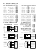
18. SERIAL COMMUNICATION OPTIONS A serial communications board may be connected to the meter main board at plug position P13 (middle position). Available boards are RS232, RS485 (with dual RJ11 connectors), RS485 Modbus (with dual RJ45 connectors), USB, USB-to-RS485 converter, Ethernet, and Ethernet-to-RS485 converter. The dual connectors of RS485 boards are wired in parallel to allow daisy chaining of addressable meters without use of a hub.
Basic Ethernet Board No jumpers needed. RS232 Board e - Normal operation. f - Slave display to RS232 from another meter. g - Pull-up resistor on RTS line. Note: Board is shipped with jumpers e and g installed RS485 Board, Full Duplex Operation b & d - Installed on last meter in long cable run. RS485 Board, Half Duplex Operation a & c - Installed for half duplex operation. d - Installed on last meter in line with long cable runs. Note: Board is shipped with no jumpers installed.
SERIAL CONNECTION EXAMPLES 45
KEYSTROKES FOR SETUP If the MENU key does not work, see Section 9 “Enabling & Locking Out Menu Items.” Press Menu Select Key .SEr 1. Fixed Parameters: No parity 8 data bits 1 stop bit Press Digit Select Key Press Value Select Key __000 Output filtering 0 Send unfiltered signal 1 Send filtered signal __000U Baud rate 0 1 2 3 4 5 6 300 baud 600 baud 1200 baud 2400 baud 4800 baud 9600 baud 19200 baud 0 1 2 3 4 5 6 7 8 9 60 Hz Line frequency 0.28 sec 0.57 sec 1.1 sec 2.3 sec 4.5 sec 9.1 sec 18.
Press Menu Select Key Press Digit Select Key Press Value Select Key _0000U Line feed 0 No line feed after carriage return 1 Line feed after carriage return _0000U Alarm data with readings 0 No alarm data 1 Alarm data with reading _0000U Control of data output 0 Continuous data output 1 Data output on ASCII command only _0000U Meter address with Custom ASCII protocol Select 1 thru F for addresses 1 thru 15. Select 0. thru F. (with decimal point) for addresses 16 thru 31.
19. EXCITATION OUTPUT & POWER SUPPLY Three isolated transducer excitation output levels are available from the power supply board. These are selectable via jumpers b, c, d, e, f in the upper right of the board, as illustrated. In addition, the board provides three jumper positions for special features. The same jumper locations apply to the universal power supply (85-264 Vac) and to the low voltage power supply (12-32 Vac or 10-48 Vdc).
20. INSTRUMENT SETUP VIA PC Instrument Setup software is a PC program which is much easier to learn than front panel programming. It is of benefit whether or not the meter is connected to a PC. With the meter connected to a PC, it allows uploading, editing and downloading of setup data, execution of commands under computer control, listing, plotting and graphing of data, and computer prompted calibration.
SETUP OF CONNECTED METER A setup file can be retrieved from the meter (DPM => Get Setup), be edited (View => Setup), be saved to disk (File => Save Setup), be retrieved from disk (File => Open Setup), and be downloaded into one or multiple meters (DPM => Put Setup). Downloading of setup files from a PC can be a major time saving when multiple meters have to be set up in the same way.
• The Readings pull-down menu provides three formats to display DPM data on the PC monitor. Use the Pause and Continue buttons to control the timing of data collection, then press Print for a hardcopy using your PC printer. - List presents the latest readings in a 20-row by 10-column table. Press Pause at any time to freeze the display. Press Print for a hardcopy. List can capture peak readings. - Plot generates a plot of readings vs. time in seconds.
21. CUSTOM CURVE LINEARIZATION Curve.exe is a DOS-based, executable PC program used to set up an Extended meter so that the readings have a user-defined, non-linear relationship with the input signal. The calculated linearizing parameters are downloaded into non-volatile memory of the meter. For example, it allows a meter to correct for transducer nonlinearity or to display volume of an irregularly shaped tank based on liquid level.
4) Equation entry mode, where the coefficients of a polynomial Y = K1X^P1 + K2X^P2 + K3*X^P3 + … are entered. Up to 20 terms are allowed. An offset can be built into X. You will be asked if your DPM has a revision of DPM4L or later. You will normally select 2 (yes), since revision DPM4L started to ship in August 2000.
22. METER CALIBRATION All analog input and analog output ranges of the meter have been digitally calibrated at the factory prior to shipment using calibration equipment certified to NIST standards. Calibration constants are stored digitally in non-volatile memory in EEPROM on the signal conditioner board and analog output board. As a result, these boards may be mixed and interchanged without requiring meter recalibration.
23. SPECIFICATIONS Meter Display Type ....................................5 LED, 7-segment, 14.2mm (.56") high digits & 3 LED indicators Color....................................................................................................................Red or green Range.................................................................... -99999 to +99999 and -99990 to +99990 A to D Conversion Technique (Pat.5,262,780)........................................................................
Thermocouple (0.1°, 1° resolution) DC Volts Range Resol. Resist. 200.00 mV 2.0000 V 20.000 V 200.00 V 300.0 V 10 µV 100 µV 1 mV 10 mV 100 mV 1 GΩ 1 GΩ 10 MΩ 10 MΩ 10 MΩ Error Type 0.01% of FS ±2 cts -210 to 760°C .01% FS ±0.09°C -347to 1400°F .01% FS ±0.16°F K -244 to 1372°C .01% FS ±0.10°C -408to 2501°F .01% FS ±0.17°F T Resol. Resist. Error 2.0000 mA 20.000 mA 200.00 mA 0.1 µA 1 µA 10 µA 100 Ω 10 Ω 1Ω 0.01% of FS ±2 cts 0.01 Ω 0.1% of FS ±5 cts 5.
Load Cell Input Range Resolution Resistance Zero Range Span Range Error 20.000 mV 50.000 mV 100.00 mV 250.00 mV 500.00 mV 1 µV 2.5 µV 5 µV 12.5 µV 25 µV 1 GΩ -99999 to 99999 0 to ±99,999 0.01% of FS ±2 cts Thermocouple Accuracy Span Tempco .........................................................................................0.003% of reading/°C ............................................................................... 0.0015% of reading/°C for load cell meter Zero Tempco ..............
Accuracy ..........................................Meter input accuracy ±0.02% of full scale analog output Resolution ...........................................................................................16 bit (1 part in 65,536) Response Time ....................................................................................... 50/60Hz update rate Scaling of Reading for Zero Output ........................................................... -99,999 to +99,999 Scaling of Reading for Full Scale Output.
24. GLOSSARY OF TERMS Adaptive Filter Threshold A threshold which causes an adaptive moving average filter to be reset to the latest reading when the accumulated difference between individual readings and the filtered reading exceeds that threshold. Adaptive moving average filtering allows a meter to respond rapidly to actual changes in signal while filtering out normal noise. The accumulated difference is also reset to zero when the latest reading has a different polarity than the filtered reading.
Deviation limits are programmed by entering menu item dEU1b for Alarm 1 and dEU2b for Alarm 2. The deviation band equals two limits. Display Blank A rear panel input which blanks the display when the input is tied to logic ground by a switch or 0V is applied (logic level true). The meter display will light when the input is open or is held at +5V (logic level false).
Menu Mode The meter programming mode used for input and range selection, meter setup, and meter configuration. Entered into from the Run mode by pressing the MENU key. The Menu mode can be locked out completely by a jumper. Meter Hold A rear panel input which freezes the meter display and all meter outputs while that input is tied to logic ground by a switch or is held at 0V (logic level true). The meter will resume operation when the input is allowed to float or is held at +5V (logic level false).
Remote Display A display mode which allows the meter to serve as a remote display to another meter when connected to it by a 4-wire phone cord. Also allows the meter to transmit raw measurement data to a computer and then display processed data from the computer. A serial communications option board is required in the meter. If such a board is not installed or no serial data is received, the meter displays rESEt. Reset There are three types of Reset: Peak and Valley Reset.
Scaling, Reading Coordinates of 2 Points Method A scaling method, where the low and high input values are determined from actual signals. A known low signal is first applied to the meter. That signal is captured as the low input value, and the desired low reading is entered. A known high signal is then applied. That signal is captured as the high input value, and the desired high reading is entered. The meter then applies straight line fit.
25. WARRANTY Laurel Electronics Inc. warrants its products against defects in materials or workmanship for a period of one year from the date of purchase. In the event of a defect during the warranty period, the unit should be returned, freight prepaid (and all duties and taxes) by the Buyer, to the authorized Laurel distributor where the unit was purchased. The distributor, at its option, will repair or replace the defective unit.