THE LAUREATE SERIES Serial Comunications Manual LAUREL Electronics Inc. 3183-G Airway Ave, Costa Mesa, CA USA 92626 Tel: (714) 434-6131 Fax: (714) 434-3766 Website: www.laurels.
CONTENTS 1.0 2.0 3.0 4.0 5.0 6.0 7.0 HARDWARE AND SOFTWARE SETUP ...........................................................................2 1.1 SELECTING THE MODULAR CABLE TYPE ..........................................................2 1.2 RS-232 AND RS-485 WIRING CONNECTIONS .....................................................3 1.3 RS-232 AND RS-485 JUMPER SETTINGS ............................................................5 1.4 SERIAL INTERFACE SETUP - ALL METERS ...............................
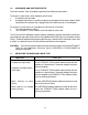
1.0 HARDWARE AND SOFTWARE SETUP The word “modular” refers to telephone-type extension cable and connections. To connect a single meter to the computer you will need: 1. A modular extension cable. 2. An adapter that contains a modular receptacle for the cable and has either a 9 pin or 25 pin subminiature D connector that is plugged into the RS485 converter in the computer. To connect 2 or more meters to a computer you will need as a minimum: 1. The same two items as above. 2.
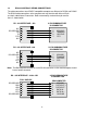
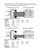
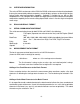
1.2 RS232 AND RS485 WIRING CONNECTIONS The cable connections to an IBM PC-compatible computer are different for RS232 and RS485. The RS232 cable connections at the computer end may interface with either a 25-pin or a 9-pin subminiature D connector. Both are commonly used and have pin connections as shown below.
Another alternative for RS-485 is to use an RS-232 to RS-485 converter that plugs into the computer RS-232 receptacle external to the computer and is powered from a +9V DC wall plugin adapter. One such unit is the B & B Electronics Model 485OT9L.
1.3 RS-232 AND RS-485 JUMPERS SETTINGS RS232 Interface Jumper g - installed for normal operation Jumper h - installed when used as a slave display with the RS232 output of another meter of the series. Jumper j - provides a pull-up resistor on the RTS line. g h j Note: The board is shipped standard with jumpers g and j installed RS232 RS485 Interface Note: Bias jumpers b and e must be installed on board for proper operation.
1.
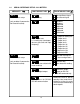
1.5 SERIAL INTERFACE SETUP - COUNTER ONLY MENU KEY DIGIT SELECT KEY Ser 3 Serial interface setup 00000 RS485 full or half duplex 0 Full duplex 1 Half duplex (only enabled if communications board installed) 00000 Meter recognition character and start & stop character 0 1 2 3 00000 RS232 RTS type 0 Nonlatching RTS 1 Latching RTS 00000 Carriage return (and LF) 0 Only at end of all items 1 At end of each item 00000 Data sent via communications (if BCD, only 1 item allowed) 0 1 2 3 4 5 1.
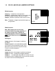
2.0 INTERFACE INFORMATION The series of DPMs and counters offers RS232 or RS485 serial communication interface boards that may be connected by cable to computers, remote displays, printers or other digital devices having similar serial communication capability. Software is available for use with an IBMcompatible PC/XT/AT computer that simplifies the logging of measurement data on the computer and provides capability for the remote setting of parameter values in lieu of using the front panel menu setup. 3.
The measurement data format with both of these parameters set consists of 10 characters: +999.99A * * * = optional character The coded character preceding the carriage return is a letter from A to P.
4.0 SYSTEM CONFIGURATIONS The meters operate in a Point-to-point mode using RS-232 or RS-485. In addition, they can operate in a Multi-point mode using RS-485. Point-to-point mode is a direct connection between a computer or other digital device and the meter. Multi-Point mode is a connection from a host computer to a multiplicity of meters bussed together with their inputs and outputs connected in parallel. For long cable runs, the last meter should have the termination resistors installed.
Counter only The transmission rate of measurement data can be selected in “Ser 1". Data transmission is initiated at the end of the calculation time following the gate time. Data is completely transmitted for one measurement before the calculation of the next measurement is started. Therefore, the reading rate is influenced by the baud rate, the number of items transmitted and gate time.
At the end of the complete transmission, the latched RTS value is reset false, even though the RTS line may be high at that instant. The RTS latch does not go true again until the RTS line is first returned to a low level after the completion of the transmission and then is taken high again. Latched control provides “print command” operation by sending a transmission for each RTS pulse. If a second pulse occurs during the transmission, it is not recognized.
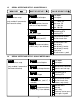
CHAR # CHARACTER DESCRIPTION 1 2 * 0-V 3 4 A-Z 0-U Command Identifier (Recognition Character) Device Address (0 addresses all devices, 1-V specific) Command Function Sub-command (or # Bytes or Words of data being transferred) CHAR 2 - ADDRESS CODES * The next table is the Serial Communication Address Codes following the “ ” for each meter address number.
COMMUNICATIONS MODE Continuous mode 1A0 Command mode 1A1 * * .
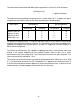
CHARACTER 4 Code for number of bytes or words Code # 1= 1 2= 2 3= 3 4= 4 5= 5 6= 6 7= 7 8= 8 Code # 9= 9 A = 10 B = 11 C = 12 D = 13 E = 14 F = 15 G = 16 Code # H = 17 I = 18 J = 19 K = 20 L = 21 M = 22 N = 23 O = 24 Code # P = 25 Q = 26 R = 27 S = 28 T = 29 U = 30 CHARACTERS 5,6 See tables in Section 6 for the RAM MEMORY ADDRESSES and NONVOLATILE MEMORY ADDRESSES with their respective data definitions.
aa is the most significant address in nonvolatile memory of the words to be read or written is n words of 2 bytes or 4 hex characters per word in order from the most to the least significant address The coded number of words n consists of a single character representing values from 1 to 30 as shown under CHARACTER 4. The most significant address aa consists of 2 hex characters as shown under NONVOLATILE MEMORY ADDRESSES. 5.4 REMOTE DISPLAY COMMAND FORMAT 5.4.1. DPM DATA FORMAT 1HSDDDDD.
S D = Sign of value, space (or +) for positive, - for neg value = Digit from 0 to 9 = Decimal point placement and must always be included A = Alarm and overload character code, A to H = Carriage return character . The following table lists the Alarm and Overload characters.
* Command Identifier “ ”, the address #, and the Command letter “H”. This is the same format that data is transmitted from a DPM in the Continuous mode. The string of characters must be exactly 8 characters plus the CR in length. SDDDDD.A No commands can be received in this mode but the front panel MENU can be accessed. Any transmissions received other than properly formatted data will result in a meaningless display.
transmits up to 3 values) each measurement cycle, Modes 8-11 provide the ability of the Remote Display to extract one of four sequential values and display it. Modes 0-5 are normal counter modes that may be commanded as follows: 1. H Command. Override the normal display reading only. 2. K Command. The value is not displayed but stored as Item 3 if Item 3 is not being used, where it may become the source, if selected, for the Alarm comparison and the Analog Output.
*# C S = = = = D = P A = = = = Recognition character Device address from 1-9, A to V, or 0 for common address. Command letter H, K, L. Sign of value, space (or +) for positive, - for neg value. Sign is o p tional in display modes 0-7, required in 8-11. Digit from 0 to 9. Number of digits may be 1-6 in display modes 07, but must be 6 in 8-11. Power of 10. 0-9, A-F where A-F represents 10-15 Optional Alarm Character as defined in section 2.
5.5 RECOGNITION CHARACTER AND START AND STOP CHARACTERS * The meter recognizes an asterisk ( ) as the command recognition character. In the counter, another command recognition character may be chosen to make the meter compatible with an existing system. The meter will still respond to an asterisk. For all meters, in continuous mode, a device ,such as a printer, may require a start and stop bit to recognize the data string being sent.
BF Analog Setup Bit 7 6 5 4 0 0 0 0 01 02 03 04 05 06 3 2 1 0 bit 0 = Analog Out Unfiltered 1 = Analog Out Filtered 0 = Current Output 1 = Voltage Output 0 0 = Not used 35 Decimal point Byte values in hex (2 hex characters/byte) XXXXX. XXXX.X XXX.XX XX.XXX X.XXXX .
31 Serial Cnfg1 (continued) Bit 7 6 5 4 3 2 1 0 Continuous Output Data Rate 0 1 1 1 18.1 21.8 1 0 0 0 36.3 43.5 1 0 0 1 72.3 86.7 0 0 0 300 baud 0 0 1 600 baud 0 1 0 1200 baud 0 1 1 2400 baud 1 0 0 4800 baud 1 0 1 9600 baud 1 1 0 19200 baud 1 = Send filtered value (0= send unfiltered value) 2F Filter Bit 7 6 5 4 3 2 1 0 0 0 0 0 0 0 0 1 Auto Filter Batch (16 samples) filter Time constant 60 Hz 50 Hz 0 0 1 0 Moving Average .07s .085s 0 0 1 1 Moving Average .14 .17 0 1 0 0 Moving Average .28 .
2C 2B Alarm Cnfg2 Alarm Cnfg1 Bit 7 6 5 4 Bit 7 6 0 0 1 1 0 1 0 1 3 2 1 0 Alarm Trigger Delay 60 Hz 50Hz 0 0 0 .018s .021s 0 0 1 .035 .043 0 1 0 .07 .085 0 1 1 .14 .17 1 0 0 .28 .34 1 0 1 .56 .68 1 1 0 1.13 1.36 1 1 1 2.27 2.
RAM HEX DATA TABLE MS A1 9E 9B 98 8F 8C 89 86 Mid A0 9D 9A 97 8E 8B 88 85 LS 9F 9C 99 96 8D 8A 87 84 Analog high value Analog low value Deviation Alarm2 Deviation Alarm1 Offset value Scale factor Setpoint 2 Setpoint 1 NONVOLATILE MEMORY ADDRESSES (2 bytes/address) See the corresponding itemsin RAM for data significance.
6.2 COUNTER 1-BYTE RAM DATA TABLE Hex Address 43 Name Resolution Bit Assignment Bit 7 6 5 4 3 2 1 0 0 1 1 0 1 1 1 0 0 1 0 1 1 1 0 1 1 1 1 0 0 0 1 0 0 1 1 0 1 0 0.00001 multiplier 0.0001 multiplier 0.001 multiplier 0.01 multiplier 0.
36 Lockout2 Bit 7 6 5 4 35 Lockout1 Bit 7 6 5 4 34 Configuration Bit 7 6 5 4 Serial Cnfg3 Display mode 0 0 0 0 0 0 0 1 0 0 1 0 0 0 1 1 0 1 0 0 0 1 0 1 0 1 1 0 0 1 1 1 1 0 0 0 1 0 0 1 1 0 1 0 1 0 1 1 1 1 0 0 Bit 7 6 5 4 33 3 2 1 0 Bit=0 is unlocked for all items 1 Change Item # locked 1 CALib locked 1 Ser 1, Ser 2, Ser 3 locked 1 An Lo, An Hi, An SEt locked 1 Front Panel meter reset locked 1 Front Panel Peak, Latched resets locked 1 View alarm setpoints locked 1 View Peak locked 3 2 1 0 Bit=0 is
33 Serial Cnfg3 (Cont'd) Bit 7 6 5 4 3 2 1 0 Transmit 1 0 0 Peak value only 1 0 1 All active items + Peak 0 Termination chars end of all items only 1 Termination chars end of each item 1 Latching RTS (0=Non-Latching RTS) 1 Custom recognition character (0 = “*” recog char) 1 Half Duplex (0 = Full Duplex) 32 Serial Cnfg2 Bit 7 6 5 4 3 2 1 0 X X X X X Counter address 0-31 (5 bits) 1 Command Mode (0 = Continuous) 1 Alarm data included with reading (0 = excluded) 1 LF following CR (0=no LF) 31 Serial Cnf
2E Setup 2B Input Type Bit 7 6 5 4 3 2 1 0 EXTIN A EXTIN B 0 0 0 0 Meter Reset Function Reset 0 0 0 1 Meter Reset Hold 0 0 1 0 Meter Reset Peak Display 0 0 1 1 Meter Reset External Gate 0 1 0 0 Function Rst Hold 0 1 0 1 Function Rst Peak Display 0 1 1 0 Function Rst External Gate 0 1 1 1 Hold Peak Display 1 0 0 0 Hold External Gate 1 0 0 1 Peak Display External Gate 1 0 1 0 Meter Rst Display Blank 1 0 1 1 Function Rst Display Blank 1 1 0 0 Hold Display Blank 1 1 0 1 Peak Display Display Blank 1 1 1 0 D
2C Alarm cnfg2 Bit 7 6 5 4 1 2B Alarm cnfg1 3 2 1 0 #Consecutive readings to Alarm 0 0 0 1 0 0 1 2 0 1 0 4 0 1 1 8 1 0 0 16 1 0 1 32 1 1 0 64 1 1 1 128 1 Alarm 1 Hysteresis (0 = Band deviation) Alarm 2 Hysteresis ( 0 = Band deviation) Bit 7 6 5 4 3 2 1 0 0 0 Alarm 1 High Active 0 1 Alarm 1 Low Active 1 0 Alarm 1 Disabled 0 0 Alarm 2 High Active 0 1 Alarm 2 Low Active 1 0 Alarm 2 Disabled 1 Alarm 1 Latching (0 = Non-Latching) 1 Alarm 2 Latching (0 = Non-Latching) 1 Relay 1 Off when Alarm 1 active (0 =
NON-VOLATILE MEMORY ADDRESSES (2 bytes/address) Sign + Magnitude XXXX XXXX XXXX XXXX XXXX XXXX S Magnitude Sign+DP+Magnitude XXXX XXXX XXXX XXXX XXXX XXXX S DP Magnitude S=Sign Sign = 1 for negative DP = 1 = DDDDDD. DP = 6 = D.DDDDD * These values are used only during Reset and are not available in RAM.
6.3 WEIGHT METER 1-BYTE RAM DATA TABLE Hex Hex Address Item Name Value 6B Configuration Bit 7 6 5 4 3 2 1 0 0 = Linear Data 1 =Custom Curve (Extended DPM) 0 = Peak of net value 1 = Peak of gross value 0 = Setpoint off set enabled 1 = Setpoint offset disabled 0 = Setup scale method 1 = Reading 2 coord method 0 0 0 = Not Rate 0 0 1 = Rate X 0.
33 Lockout1 Bit 7 6 5 4 3 2 1 0 bit = 0 is unlocked for all items 1 = Count locked 1 = Setup, config and dEC.
2F Filter Bit 7 6 5 4 3 2 1 0 0 0 0 0 0 0 0 1 Auto Filter Batch (16 samples) filter Time constant 60 Hz 50 Hz 0 0 1 0 Moving Average .07s .085s 0 0 1 1 Moving Average .14 .17 0 1 0 0 Moving Average .28 .34 0 1 0 1 Moving Average .57 .68 0 1 1 0 Moving Average 1.13 1.36 0 1 1 1 Moving Average 2.27 2.72 1 0 0 0 Moving Average 4.53 5.44 1 0 0 1 Moving Average 9.06 10.
2C Alarm Cnfg2 Bit 7 6 5 4 0 0 0 0 2B Alarm Cnfg1 0 0 0 0 0 0 0 0 0 0 1 1 3 2 1 0 0 1 0 1 Alarm Trigger Delay 60 Hz 50Hz 0 0 0 .018s .021s 0 0 1 .035 .043 0 1 0 .07 .085 0 1 1 .14 .17 1 0 0 .28 .34 1 0 1 .56 .68 1 1 0 1.13 1.36 1 1 1 2.27 2.
Hex Addresses MS A1 9E 9B 98 8F 8C 89 86 E4 Mid A0 9D 9A 97 8E 8B 88 85 E3 LS 9F 9C 99 96 8D 8A 87 84 E2 Analog high value Analog low value Deviation Alarm2 Deviation Alarm1 Offset value Scale factor Setpoint 2 Setpoint 1 Tare value NON-VOLATILE MEMORY ADDRESSES (2 bytes/address) See the corresponding items above for data significance.
7.0 SOURCE LISTING B & B Electronics Manufacturing Co. 707 Dayton Road Ottawa, IL 61350 Phone: (815) 433-5100 Fax: (815) 433-5109 Website: www.bb-elec.com B & B manufactures a variety RS485 to RS232 converters and RS232 and RS485 to USB converters. They also have RJ11 to 9 pin adapters . The Model 485OT9L is the recommended RS485 to RS232 converter.
WARRANTY Laurel Electronics Inc. warrants its products against defects in materials or workmanship for a period of one year from the date of purchase. In the event of a defect during the warranty period, the unit should be returned, freight prepaid (and all duties and taxes) by the Buyer, to the authorized Laurel distributor where the unit was purchased. The distributor, at its option, will repair or replace the defective unit.
Copyright 1996-2004 Laurel Electronics Inc. 06/04 Rev.