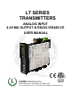
LT SERIES TRANSMITTERS ANALOG INPUT 4-20 MA OUTPUT & RS232 / RS485 I/O USER MANUAL LAUREL Electronics Inc. 3183-G Airway Ave, Costa Mesa, CA, 92626, USA Tel: (714) 434-6131 • Fax: (714) 434-3766 • Website: www.laurels.
1. ORDERING GUIDE Configure a model number in this format: LT20DCV1, CBL04 Transmitter Type RMS Volts RTD Temperature LT......4-20 mA, 0-20 mA or 010V isolated analog output, isolated RS232 or RS485 serial data output, two 120 mA solid state relays, and isolated transducer excitation output. RMV1 ...................... 200.00 mV RMV2 ......................... 2.0000 V RMV3 ......................... 20.000 V RMV4 ......................... 200.00 V RMV5 ........................... 600.0 V Pt100, P385C ..
2. TABLE OF CONTENTS 1. ORDERING GUIDE ............................................................................................................ 2 2. TABLE OF CONTENTS ....................................................................................................... 3 3. PRODUCT OVERVIEW....................................................................................................... 4 4. RECEIVING & UNPACKING YOUR TRANSMITTER ...........................................................
3. PRODUCT OVERVIEW This manual covers LT Series DIN rail transmitters with isolated 4-20 mA and RS232/RS485 outputs, dual relays, and and an analog input signal conditioner. A separate manual covers LTE Series DIN rail transmitters with isolated 4-20 mA and Ethernet outputs, dual relays, and an analog input signal conditioner.
4. RECEIVING & UNPACKING YOUR TRANSMITTER Your transmitter was carefully tested and inspected prior to shipment. Should the transmitter be damaged in shipment, notify the freight carrier immediately. In the event the transmitter is not configured as ordered or is inoperable, return it to the place of purchase for repair or replacement. Please include a detailed description of the problem. 5.
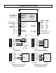
. TRANSMITTER FIELD WIRING 1 See manuals 2 for different 3 signal types 4 5 6 Control input 2 Control input 1 GND Analog out Analog out + 1 2 3 1 2 AL2 AL2 AL1 AL1 1 2 3 4 6 5 4 3 2 1 TX RX NC GND BRX N/C Transmitter P6 Signal input & excitation output Signal conditioner board P2 Serial data I/O P4 Analog output P3 Solid state relays 5 4 3 2 1 9 8 7 6 DB9 connector to PC (rear view) N/C ARX / ATX N/C GND BRX / BTX N/C Transmitter 6 5 4 3 2 1 RS232 TX RX NC GND GND N/C 3 Power GND 2 AC ne
P6 - SIGNAL INPUT DETAIL DC & Externally Powered Process Excitation return + Excitation - Signal input + Signal input 1 2 3 4 -DC +DC 2-Wire Process Transmitter Excitation return + Excitation - Signal input + Signal input 1 2 3 4 Load Cell Excitation return - Sense - Signal + Signal + Excitation + Sense 1 2 3 4 5 6 For 4-wire load cell connection, jumper Pin1 to Pin 2, and Pin 5 to Pin 6.
7. PROGRAMMING YOUR TRANSMITTER OVERVIEW Our transmitters are easily programmed using a PC with an RS232 port and Instrument Setup (IS) software, which provides a graphical user interface. The software allows uploading, editing, downloading and saving of setup data, execution of commands under computer control, listing, plotting and graphing of data, and computer prompted calibration. USING IS SOFTWARE Use a 3-wire RS232 cable (P/N CBL04) to connect your transmitter to the COM port of your PC.
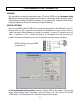
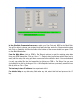
In the Establish Communications screen, select your Com Port and 9600 as the Baud Rate. You will be able to change your protocol and baud rate later under the Communication setup tab. Click on Establish, and the two fields at the bottom of the screen should turn green. Click on the Main Menu button. From the Main Menu, click on DPM => Get Setup to retrieve (or get) the existing setup data from your DPM transmitter.
Click on DPM => Get Setup to retrieve the current setup information from your DPM transmitter, then on View => Setup, which will take you to the Input+Display tab. Use this screen to set up Signal Input, Display, and Control Inputs. The software reads the signal conditioner type, but not the range, which is set by jumpers. 50/60 Hz Line Freq is used for noise rejection. Click on the Scaling tab to scale your transmitter.
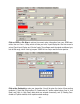
Click on the Filter tab to set to set up filtering for your readings. The filter time constant can be automatic, be specified in seconds, or be turned off. The adaptive threshold modifies the time constant in response to noise. A low adaptive threshold is recommended for normal low noise. A high adaptive threshold is recommended for high noise environments. Click on the Relay Alarms tab to set up your transmitter’s two solid state relays, which are standard.
Click on the Communication tab to view the communication parameters that you used to establish default communications with your transmitter. You can reselect Baud Rate, Device Address, Serial Protocol, and Full/Half Duplex, even though you may have selected different values to establish initial communications with your PC. Click on the Analog Out tab to scale your analog output, which is standard. Under Range, select 0-20 mA Current, 0-10V Voltage, or 4-20 mA.
ADDITIONAL FEATURES • The Commands pull-down menu allows you to execute certain functions by using your computer mouse. This menu will be grayed out unless a Get Setup has been executed. • The Readings pull-down menu provides three formats to display input data on your PC monitor. Use the Pause and Continue buttons to control the timing of data collection, then press Print for a hardcopy on your PC printer. - List presents the latest internal readings in a 20-row by 10-column table.
Graph • The Jumpers pull-down menu shows jumper positions for the selected signal conditioner boards and the main board, duplicating information in this manual.
8. OPENING YOUR TRANSMITTER CASE WHEN TO CHANGE JUMPERS Most users will never have the need to open the transmitter case. The transmitters are shipped fully jumpered and ready for scaling. The signal conditioner type, range and temperature sensor are specified by the model number on the transmitter label. To select a different signal conditioner range, you may open the transmitter case and change jumper settings. Your selected range should encompass your maximum expected signal levels.
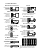
9. DC SIGNAL CONDITIONER BOARD JUMPER SETTINGS Five voltage and four current ranges are jumper selectable. These also have to be selected in Instrument Setup software. Board Revisions Q and R Voltage Ranges Jumpers FS Input E1 E2 E3 ±200.00 mV ±2.0000 V ±20.000 V ±200.00 V ±300V (UL) ±600V (not UL) A A B B B B f f h h g g b a b a a a Current Ranges B E1 A h b E3 Jumpers a E2 g b a FS Input E1 E2 E3 f c ±2.0000 mA ±20.000 mA ±200.00 mA ±5.
10. AC RMS SIGNAL CONDITIONER BOARD JUMPER SETTINGS Five voltage and four current ranges are jumper selectable. These also have to be selected in Instrument Setup software. Board Revision S Voltage Ranges 200.00 mV 2.0000 V 20.000 V 200.00 V 600.00 V Current Ranges 2.0000 mA 20.000 mA 200.00 mA 5.
11. LOAD CELL SIGNAL CONDITIONER BOARD JUMPER SETTINGS Five ranges are jumper selectable. These also have to be selected in Instrument Setup software. Load Cell & Microvolt Ranges FS Input Jumpers ±20.000 mV ±50.000 mV ±100.00 mV ±250.00 mV ±500.00 mV e a b c d 1. Use 2.5 mm (0.1") jumpers. 2. Store spare jumpers on an unused jumper post.
12. THERMOCOUPLE SIGNAL CONDITIONER BOARD JUMPER SETTINGS Seven thermocouple types are jumper selectable. These also have to be selected in Instrument Setup software. PNP transistor Board Revision A Thermocouple Type J, K, E, N T, R, S Open T/C Indication Upscale Downscale J5-X E4 Jumper none j J5-Y E3 Jumper E3 h i h i 1. Use 2.5 mm (0.1") jumpers. 2. Store spare jumpers on an unused jumper post.
13. RTD & OHMS SIGNAL CONDITIONER BOARD JUMPER SETTINGS The same signal conditioner board is used for 4 RTD types and 5 resistance ranges, as selected by jumpers. Corresponding selections also have to be made in Instrument Setup software. With RTDs, display in °C or °F and resolution of 1°, 0.1° or 0.01° are user programmable. 0.01° resolution should only be used for relative readings, not absolute readings, and with software selectable digital filtering.
14. MAIN BOARD JUMPER SETTINGS d b a E6 c a E4 b E1 E3 E2 Serial Signal RS485 RS232 c b a a b d c Duplex Jumpers Termination Resistor* Full None E6 a = Transmit E6 c = Receive Half E6 b + d** E6 c Full None None * The termination resistor jumper settings should only be selected if the transmitter is the last device on an RS485 line longer than 200 feet (60 m). ** Or jumper external BTX to BRX and ATX to ARX (same effect as internal jumpers).
15. DUAL RELAY OPERATION Dual solid state relays are standard and can operate in a basic alarm mode, in a hysteresis band mode, or in a deviation band mode. Setpoint operation is referenced to the digital reading in engineering units that is internal to the transmitter.
16. INPUT SIGNAL FILTERING A moving average filter is selectable in software to process the internal digital readings, which are taken at 60/sec with 60 Hz power and 50/sec with 50 Hz power. Eight settings are selectable with t equivalent RC time constants from 0.08 sec to 9.6 sec. The longer time constants provide superior noise filtering at the expense of fast response time.
18. CUSTOM CURVE LINEARIZATION Curve.exe is a DOS-based, executable PC program used to set up an Extended transmitter so that the internal digital readings have a user-defined, non-linear relationship with the input signal. For example, it allows a transmitter to correct for transducer nonlinearity. Calculated linearizing parameters are downloaded from a PC into non-volatile memory of the transmitter.
19. MODBUS PROTOCOL TRANSMITTER COMMUNICATIONS 1.0 GENERAL The Modbus capability conforms to the Modbus over Serial Line Specification & Implementation guide, V1.0. Both the Modbus RTU and Modbus ASCII protocols are implemented. This 5-page manual section presents key programmable Modbus features. Our detailed Modbus manual can be downloaded from http://www.laurels.com/downloadfiles/modbus.pdf Modbus RTU Baud Rate........... 300, 600, 1200, 2400, 4800, 9600 or 19200 Data Format .......
4.0 COMMUNICATIONS SETUP Parameters selectable via Instrument Setup software, distributed on CD ROM: Serial Protocol ...............................Custom ASCII, Modbus RTU, Modbus ASCII Modbus ASCII Gap Timeout...........1 sec, 3 sec, 5 sec, 10 sec Baud Rate.......................................300, 600, 1200, 2400, 4800, 9600, 19200 Parity .............................................No parity, odd parity, even parity Device Address .............................0 to 247 5.
FC08: Diagnostics Checks communications between the Master and Slave, and returns the count in the Modbus Slave counters (which are reset when the meter is reset). Hex Sub Function Code Data Send Response Data 00 00 Any Same as sent 00 01 Description Returns Query Data (N x 2 bytes). Echo Request. Restarts Communications. If in the Listen-Only mode, no response occurs. Takes Slave out of the Listen-Only mode and one of the following: Clears communications event counters.
6.0 SUPPORTED EXCEPTION RESPONSE CODES Code Name Error Description ---- -------------------- -----------------------------------------------------01 Illegal Function Illegal Function Code for this Slave. Only hex Function Codes 03, 04, 05, 08, 10 (dec 16) are allowed. 02 Illegal Data Address Illegal Register Address for this Slave. 03 Illegal Data Value Illegal data value or data length for the Modbus protocol. 04 Slave Device Failure Slave device failure (eg. Transmitter set for external gate). 7.
Modbus ASCII Format FC Action 03 03 Byte Number 1 2 3 Request Response : : MA MA FC FC RA RA NR NR LRC CR NB DD* DD* LRC CR LF LF 04 04 Request Response : : MA MA FC FC RA RA NR NR LRC CR NB DD* DD* LRC CR LF LF 05 05 Request Response : : MA MA FC FC RA RA RA WW WW LRC CR RA WW WW LRC CR LF LF 08 08 Request Response : : MA MA FC FC SF SF SF SF WW WW LRC CR DD DD LRC CR LF LF 10 10 Request Response : : MA MA FC FC RA RA RA RA NR NR : MA FC +80 EC LRC CR Excepti
20. CUSTOM ASCII PROTOCOL TRANSMITTER COMMUNICATIONS 1.0 SERIAL COMMUNICATION FORMAT Mode ................ Full Duplex (Separate transmit and receive lines) and Half Duplex (RS485 only) Baud Rate ......... 300, 600, 1200, 2400, 4800, 9600, 19200 selectable with Instrument Setup software. Parity ................ None Word length ...... 8 data bits Stop bit ............ 1 The Custom ASCII protocol is simpler than the Modbus protocol. This 5-page manual section provides some of its key programmable features.
Values are transmitted in a continuous string with no intervening spaces. If the 5th digit in is set to 1 using Instrument Setup software, the termination characters of and optional appear after each value. If the 5th digit is et to 0, the termination characters appear only once at the end of the string. In either case, if included, the coded character appears at the end of the last value only. 3.
Char # Character 1 2 3 4 * 0-V A-Z 0-U Description Command Identifier. Recognition Character. Device Address. 0 addresses all devices, 1-V specific devices. Command Function Sub-command. Number of Bytes of RAM or Words (2 Bytes) of non-volatile memory data being transferred. CHAR 2 - Address Codes A Serial Communications Address Code from 1 to V follows the “*” to indicate the device address number from 1 to 31.
Peak value reset Remote display reset Valley reset Tare function Tare reset 6.0 *1C3 *1C4 *1C9 *1CA *1CB READING AND WRITING TO RAM AND NONVOLATILE MEMORY CHAR 1, 2: The Recognition character and Meter Address Code are the same as shown in previous table.
General, Reading and Writing Ram Memory Data RAM memory data is read and written as a continuous string of bytes consisting of 2 hex characters (0-9,A-F) per byte. Included in the command are the total number of bytes to be transferred and the most significant address in RAM of the continuous string of bytes. The format is: Read lower RAM data Write lower RAM data Read upper RAM data Write upper RAM data where: n aa *1Gnaa *1Fnaa *1Rnaa *1Qnaa is the number of bytes to be read or written.
21. LT SERIES ANALOG INPUT TRANSMITTER SPECIFICATIONS Mechanical Case dimensions..........................................................................................120 x 101 x 22.5 mm Case mounting................................................................................ 35 mm DIN rail per EN 50022 Electrical connections ..............................................................Detachable screw plug connectors Environmental Operating temperature...............................................
Input Signal Noise Rejection CMV, DC to 60 Hz .........................................................................................................250V RMS CMR, DC to 60 Hz...............................................................................................................130 dB NMR at 50/60 Hz ............................................................................. 90 dB with no digital filtering Input filtering ......................................
Load Cell & Microvolt Input Range Input Resistance Input Error ±20.000 mV ±50.000 mV ±100.00 mV ±250.00 mV ±500.00 mV 1 GΩ 0.01% of FS ±2 counts Max applied voltage ..............................................................................................................100 V RTD Input (1°, 0.1° or 0.01° resolution) Type Excitation Range Conformity Error Platinum, Pt100 =.00385 (DIN) 256 µA -202 to 850°C -331 to 1562°F 0.03°C 0.05°F Platinum, Pt100 =.
Over-voltage protection .................................................................................................... 125 Vac Open sensor indication ..............................................0 mA or > 20 mA output, jumper selectable Type Range Conformity Error J -210 to 760°C -347to 1400°F 0.09°C 0.16°F K -244 to 1372°C -408to 2501°F 0.10°C 0.17°F T 0 to 400°C -257 to 0°C 32 to 752°F -430 to 32°F 0.03°C 0.20°C 0.05°F 0.36°F E -240 to 1000°C -400 to 1830°F 0.18°C 0.
- 39 -
22. WARRANTY Laurel Electronics Inc. warrants its products against defects in materials or workmanship for a period of one year from the date of purchase. In the event of a defect during the warranty period, the unit should be returned, freight prepaid (and all duties and taxes) by the Buyer, to the authorized Laurel distributor where the unit was purchased. The distributor, at its option, will repair or replace the defective unit.