LTA “DPM” SERIES TRANSMITTERS ANALOG INPUT 4-20 mA, 0-20 mA or 0-10V ANALOG OUTPUT OWNERS MANUAL LAUREL Electronics Inc. 3183-G Airway Ave, Costa Mesa, CA, 92626, USA Tel: (714) 434-6131 Fax: (714) 434-3766 Website: www.laurels.
1. ORDERING GUIDE, LTA “DPM” SERIES TRANSMITTERS Configure a model number in this format: LTA202DCV1, CBL04 LTA Laureate analog input transmitter with 4-20 mA, 0-20 mA or 0-10V isolated analog output. Includes serial port for programming and isolated 5, 10 or 24V excitation output. Default jumpered for RS232 and 10V excitation. Process Signals 4-20 mA, 0-10V, etc. Strain Gauge, Potentiometer Main Board 2................ Standard main board 4................ Extended main board Pt100, P385C .....
2. TABLE OF CONTENTS 1. ORDERING GUIDE, 4-20 MA OUTPUT “DPM” SERIES TRANSMITTERS.......................... 2 2. TABLE OF CONTENTS ....................................................................................................... 3 3. INTRODUCTION, 4-20 MA OUTPUT “DPM” SERIES TRANSMITTERS.............................. 4 4. RECEIVING & UNPACKING YOUR TRANSMITTER ........................................................... 5 5. SAFETY CONSIDERATIONS ...............................................
3. INTRODUCTION, 4-20 MA “DPM” SERIES TRANSMITTERS This manual covers DIN rail transmitters with a 4-20 mA, 0-20 mA or 0-10V output and an analog input. The transmitters duplicate the signal conditioning and signal processing features of 1/8 DIN size, digital panel meter (DPM) counterparts for exceptional accuracy at high read rate. The current and voltage transmitter outputs are jumper selectable and are transformer isolated to avoid ground loops.
4. RECEIVING & UNPACKING YOUR TRANSMITTER Your transmitter was carefully tested and inspected prior to shipment. Should the transmitter be damaged in shipment, notify the freight carrier immediately. In the event the transmitter is not configured as ordered or is inoperable, return it to the place of purchase for repair or replacement. Please include a detailed description of the problem. 5.
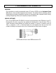
. TRANSMITTER FIELD WIRING 1 See manuals 2 for different 3 signal types 4 5 6 Analog out - 1 Analog out + 2 AL2 AL2 AL1 AL1 6 5 4 3 2 1 1 2 3 4 TX RX NC GND BRX N/C Transmitter P6 Signal input & excitation output Signal conditioner board P4 Analog output P2 Serial data I/O P3 Solid state relays 5 4 3 2 1 9 8 7 6 DB9 connector to PC (rear view) N/C ARX / ATX N/C GND BRX / BTX N/C Transmitter 6 5 4 3 2 1 RS232 TX RX NC GND GND N/C 3 Power GND 2 AC neutral or -DC 1 AC high or +DC P1 Power
P6 - SIGNAL INPUT DETAIL DC & Externally Powered Process Excitation return + Excitation - Signal input + Signal input 1 2 3 4 -DC +DC 2-Wire Process Transmitter Excitation return + Excitation - Signal input + Signal input 1 2 3 4 Load Cell Excitation return - Sense - Signal + Signal + Excitation + Sense 1 2 3 4 5 6 For 4-wire load cell connection, jumper Pin1 to Pin 2, and Pin 5 to Pin 6.
7. PROGRAMMING YOUR TRANSMITTER OVERVIEW Our transmitters are easily programmed using a PC with an RS232 port and Instrument Setup (IS) software, which provides a graphical user interface. The software allows uploading, editing, downloading and saving of setup data, execution of commands under computer control, listing, plotting and graphing of data, and computer prompted calibration. USING IS SOFTWARE Use a 3-wire RS232 cable (P/N CBL04) to connect your transmitter to the COM port of your PC.
In the Communications Setup screen, select the Custom ASCII as the protocol, as this is the factory default setting. Select Transmitter LTA, LTM, LTS as the Device Type. Then click on the RS-232 (USB) button. This will take you to the Establish Communications screen.
In the Establish Communications screen, select your Com Port and 9600 as the Baud Rate. You will be able to change your protocol and baud rate later under the Communication setup tab. Click on Establish, and the two fields at the bottom of the screen should turn green. Click on the Main Menu button. From the Main Menu, click on DPM => Get Setup to retrieve (or get) the existing setup data from your DPM transmitter.
Click on DPM => Get Setup to retrieve the current setup information from your DPM transmitter, then on View => Setup, which will take you to the Input+Display tab. Use this screen to set up Signal Input, Display, and Control Inputs. The software reads the signal conditioner type, but not the range, which is set by jumpers. 50/60 Hz Line Freq is used for noise rejection. Click on the Scaling tab to scale your transmitter.
Click on the Filter tab to set to set up filtering for your readings. The filter time constant can be automatic, be specified in seconds, or be turned off. The adaptive threshold modifies the time constant in response to noise. A low adaptive threshold is recommended for normal low noise. A high adaptive threshold is recommended for high noise environments. Click on the Relay Alarms tab to set up your transmitter’s two solid state relays, which are standard.
Click on the Communication tab to view the communication parameters that you used to establish default communications with your transmitter. You can reselect Baud Rate, Device Address, Serial Protocol, and Full/Half Duplex, even though you may have selected different values to establish initial communications with your PC. Click on the Analog Out tab to scale your analog output, which is standard. Under Range, select 0-20 mA Current, 0-10V Voltage, or 4-20 mA.
ADDITIONAL FEATURES • The Commands pull-down menu allows you to execute certain functions by using your computer mouse. This menu will be grayed out unless a Get Setup has been executed. • The Readings pull-down menu provides three formats to display input data on your PC monitor. Use the Pause and Continue buttons to control the timing of data collection, then press Print for a hardcopy on your PC printer. - List presents the latest internal readings in a 20-row by 10-column table.
Graph • The Jumpers pull-down menu shows jumper positions for the selected signal conditioner boards and the main board, duplicating information in this manual.
8. OPENING YOUR TRANSMITTER CASE WHEN TO CHANGE JUMPERS Most users will never have to open the transmitter case. The transmitters are shipped fully jumpered and ready for scaling via Instrument Setup software. The factory configuration is specified by the model number on the transmitter label. Jumpers on the signal board set the signal range. To move jumpers, you will need to open the transmitter. Your selected range should encompass your maximum expected signal levels.
9. DC SIGNAL CONDITIONER BOARD JUMPER SETTINGS Five voltage and four current ranges are jumper selectable. These also have to be selected in Instrument Setup software. Board Revision N Voltage Ranges E1 E2 E3 ±200.00 mV ±2.0000 V ±20.000 V ±200.00 V ±600.00 V A A B B B f f h h g b a b a a Current Ranges E1 E2 E3 h b b b b g ±2.0000 mA ±20.000 mA ±200.00 mA ±5.000 A A A A A e, h d, h c, h a, b, h B A a f e Board Revision P Voltage Ranges Jumpers FS Input E1 E2 ±200.00 mV ±2.
10. AC RMS SIGNAL CONDITIONER BOARD JUMPER SETTINGS Five voltage and four current ranges are jumper selectable. These also have to be selected in Instrument Setup software. Voltage Ranges 200.00 mV 2.0000 V 20.000 V 200.00 V 600.00 V Current Ranges 2.0000 mA 20.000 mA 200.00 mA 5.
11. LOAD CELL SIGNAL CONDITIONER BOARD JUMPER SETTINGS Five ranges are jumper selectable. These also have to be selected in Instrument Setup software. Load Cell & Microvolt Ranges FS Input Jumpers ±20.000 mV ±50.000 mV ±100.00 mV ±250.00 mV ±500.
12. THERMOCOUPLE SIGNAL CONDITIONER BOARD JUMPER SETTINGS Seven thermocouple types are jumper selectable. These also have to be selected in Instrument Setup software. Thermocouple Type J, K, E, N T, R, S Open T/C Indication Upscale Downscale E4 Jumper none j E3 Jumper h i 1. Use 2.5 mm (0.1") jumpers. 2. Store spare jumpers on an unused jumper post.
13. RTD & OHMS SIGNAL CONDITIONER BOARD JUMPER SETTINGS The same signal conditioner board is used for 4 RTD types and 5 resistance ranges, as selected by jumpers. Corresponding selections also have to be made in Instrument Setup software. With RTDs, display in °C or °F and resolution of 1°, 0.1° or 0.01° are user programmable. 0.01° resolution should only be used for relative readings, not absolute readings, and with software selectable digital filtering.
14. MAIN BOARD JUMPER SETTINGS d b a E6 c a E4 b E1 E3 E2 Serial Signal RS485 RS232 c b a a b d c Duplex Jumpers Termination Resistor* Full None E6 a = Transmit E6 c = Receive Half E6 b + d** E6 c Full None None * The termination resistor jumper settings should only be selected if the transmitter is the last device on an RS485 line longer than 200 feet (60 m). ** Or jumper external BTX to BRX and ATX to ARX (same effect as internal jumpers).
15. DUAL RELAY OPERATION The dual solid state relays can operate in a basic alarm mode, in a hysteresis band mode, or in a deviation band modes, as explained below. Setpoint operation is referenced to the digital reading in engineering units that is internal to the transmitter. For example, temperature alarm or control would be referenced to a setpoint in °C or °F.
hysteresis band is often used to minimize relay chatter. A wide hysteresis band can be used for on-off control applications. A deviation band alarm controls relay action symmetrically around a setpoint. The relay actuates when the reading falls within the deviation band, and de-actuates when the reading falls outside. A deviation value (such as 50 counts) is set up around both sides of the setpoint to create the deviation band. Passbands around a setpoint are often used for component testing.
16. INPUT SIGNAL FILTERING A moving average filter is selectable in software to process the internal digital readings, which are taken at 60/sec with 60 Hz power and 50/sec with 50 Hz power. Eight moving average settings are selectable with the following equivalent RC time constants: 0.08 sec, 0.15 sec, 0.3 sec, 0.6 sec, 1.2 sec, 2.4 sec, 4.8 sec, 9.6 sec. The longer time constants provide superior noise filtering at the expense of fast response time.
17. TRANSMITTER CALIBRATION All input ranges are calibrated at the factory using NIST certified calibration equipment, and the calibration constants are stored digitally in EEPROM on the signal conditioner board. This allows signal ranges and signal conditioner boards to be changed in the field without transmitter recalibration. Calibration constants for analog outputs are stored in EEPROM on the main board.
18. CUSTOM CURVE LINEARIZATION Curve.exe is a DOS-based, executable PC program used to set up an Extended transmitter so that the analog output and internal digital readings have a user-defined, non-linear relationship with the input signal. For example, it allows a transmitter to correct for transducer nonlinearity or to transmit the volume of an irregularly shaped tank based on liquid level. The calculated linearizing parameters are downloaded into non-volatile memory of the transmitter.
19. 4-20 MA “DPM” SERIES TRANSMITTER SPECIFICATIONS Mechanical Case dimensions..........................................................................................120 x 101 x 22.5 mm Case mounting................................................................................ 35 mm DIN rail per EN 50022 Electrical connections ..............................................................Detachable screw plug connectors Environmental Operating temperature.................................................
Input Signal Noise Rejection CMV, DC to 60 Hz .........................................................................................................250V RMS CMR, DC to 60 Hz...............................................................................................................130 dB NMR at 50/60 Hz ............................................................................. 90 dB with no digital filtering Input filtering ......................................
Load Cell & Microvolt Input Range Input Resistance Input Error ±20.000 mV ±50.000 mV ±100.00 mV ±250.00 mV ±500.00 mV 1 GΩ 0.01% of FS ±2 counts Max applied voltage ..............................................................................................................100 V RTD Input (1°, 0.1° or 0.01° resolution) Type Excitation Range Conformity Error Platinum, Pt100 =.00385 (DIN) 256 µA -202 to 850°C -331 to 1562°F 0.03°C 0.05°F Platinum, Pt100 =.
Over-voltage protection .................................................................................................... 125 Vac Open sensor indication ..............................................0 mA or > 20 mA output, jumper selectable Type Range Conformity Error J -210 to 760°C -347to 1400°F 0.09°C 0.16°F K -244 to 1372°C -408to 2501°F 0.10°C 0.17°F T 0 to 400°C -257 to 0°C 32 to 752°F -430 to 32°F 0.03°C 0.20°C 0.05°F 0.36°F E -240 to 1000°C -400 to 1830°F 0.18°C 0.
20. WARRANTY Laurel Electronics Inc. warrants its products against defects in materials or workmanship for a period of one year from the date of purchase. In the event of a defect during the warranty period, the unit should be returned, freight prepaid (and all duties and taxes) by the Buyer, to the authorized Laurel distributor where the unit was purchased. The distributor, at its option, will repair or replace the defective unit.