LTE SERIES TRANSMITTERS Analog Input, Ethernet & Isolated 4-20 mA Outputs USER MANUAL LAUREL Electronics Inc. 3183-G Airway Ave, Costa Mesa, CA, 92626, USA Tel: (714) 434-6131 • Fax: (714) 434-3766 • Website: www.laurels.
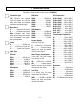
1. ORDERING GUIDE Configure a model number in this format: LTE20DCV1 Transmitter Type RMS Volts RTD Temperature LTE.... Ethernet and isolated 4-20 mA, outputs, two 120 mA solid state relays, and isolated transducer excitation output. RMV1 ...................... 200.00 mV RMV2 ......................... 2.0000 V RMV3 ......................... 20.000 V RMV4 ......................... 200.00 V RMV5 ........................... 600.0 V Pt100, P385C .....-202 to 850°C Pt100, P385F ...
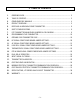
2. TABLE OF CONTENTS 1. ORDERING GUIDE ............................................................................................................ 2 2. TABLE OF CONTENTS ....................................................................................................... 3 3. COMPLEMENTARY MANUALS ......................................................................................... 4 4. PRODUCT OVERVIEW...........................................................................................
3. COMPLEMENTARY MANUALS This manual covers LTE Series DIN rail transmitters with isolated Ethernet and 4-20 mA outputs, dual relays, and an analog input signal conditioner. It covers hardware aspects such a pinout and onboard jumpers, and transmitter setup such as scaling and relay setpoints. It also presents the main commands and text strings to be used with the Modbus and Custom ASCII communications protocols. It is intended to be used with the following separate manuals: • Ethernet Manual.
4. PRODUCT OVERVIEW LTE Series transmitters duplicate the signal conditioning and signal processing features of their 1/8 DIN panel-mounted digital panel meter counterparts for exceptional accuracy at high read rates. A wide range of analog signal sources are accommodated by five analog signal conditioners, which are the same as for our panel meters: • DC input for volts, amps, process signals (e.g., 4-20 mA), and strain gauges. Most sensitive full scale input range of 200 mV. Built-in 5A current shunt.
5. RECEIVING & UNPACKING YOUR TRANSMITTER Your transmitter was carefully tested and inspected prior to shipment. Should the transmitter be damaged in shipment, notify the freight carrier immediately. In the event the transmitter is not configured as ordered or is inoperable, return it to the place of purchase for repair or replacement. Please include a detailed description of the problem. 6.
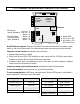
. LTE TRANSMITTER MAIN BOARD JUMPERS & FIELD WIRING E1 E4 P5 Signal input & excitation output Signal conditioner board RJ45 E2 P4 Analog Ana out output (standard) Ana out + Alarm 2 P3 Solid state Alarm 2 relays (normally Aalrm 1 open, standard) Alarm 1 1 2 1 2 3 4 d c b a a b E3 b Ethernet a E7 c b a 3 Earth GND 2 AC neut or -DC 1 AC high or +DC P1 Power input An RJ45 Ethernet connector allows the transmitter to be connected directly to a computer, router, switch or hub via an Ethernet cabl
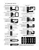
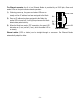
P6 - SIGNAL INPUT DETAIL DC & Externally Powered Process Excitation return + Excitation - Signal input + Signal input 1 2 3 4 -DC +DC 2-Wire Process Transmitter Excitation return + Excitation - Signal input + Signal input 1 2 3 4 Load Cell Excitation return - Sense - Signal + Signal + Excitation + Sense 1 2 3 4 5 6 For 4-wire load cell connection, jumper Pin1 to Pin 2, and Pin 5 to Pin 6.
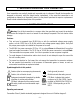
The Ethernet connector for all of our Ethernet Nodes is provided by an RJ45 jack, Green and amber LEDs on the jack indicate network operation: 1) Following power-up, the green and amber LEDs are on steady until an IP address has been assigned to the Node. 2) Once an IP address has been assigned to the Node, the amber LED is turned off. It will light up whenever the Node detects data packet activity.
8. PROGRAMMING YOUR TRANSMITTER OVERVIEW LTE transmitters are easily programmed by connecting them to the same LAN as a PC or by connecting them directly to a PC with an Ethernet cable, and then running Instrument Setup Software on the PC. This MS Windows based software allows Node and Device discovery, uploading, editing, downloading and saving of setup data, execution of commands under computer control, listing, plotting and graphing of data, and computer prompted calibration.
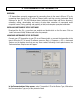
Upon clicking on Ethernet for the first time, you may be presented with the Windows Security Alert shown below. Click on Unblock, and IS software will be launched. If you ever click on Keep Blocking, IS software will not be able to establish Ethernet communications. You will then need to restore Windows Firewall defaults by clicking on Control Panel => Windows Firewall => Advanced => Restore Defaults. The Node Discovery tab under Node Setup will open once you have passed the Windows Firewall.
Click on the Device Discovery tab, and all Devices attached to your Node will be listed. With an LTE transmitter, the transmitter will be the only Device listed. With a device server Node, there can be up to 30 Devices (meters and transmitters) on an RS485 bus. Please see our Ethernet manual. Highlight your Node, and you can assign a descriptive name to it, such as Tank Farm. The default name is the Node’s unique MAC address. You can also use this tab to change your Node’s communication settings.
Click on the Advanced Settings tab, and you will be given the opportunity to change the Node’s TCP and UDP Port settings. Press Get to retrieve settings from the Node to the PC. Press Put to write settings from the PC to the Node. If a browser is to access our Nodes on a remote LAN over the Internet, port forwarding must first be set up for the router that controls the remote LAN. The default port numbers programmed into our Nodes are UDP port 63179 for Node discovery and TCP port 502 for Modbus TCP.
To reach the above Input+Display tab screen, follow this procedure: 1) Highlight your device under the Device Discovery tab. 2) Click on the Main Menu button. A new DPM Main Menu window will open with a help screen. 3) Click on DPM in the top menu bar. Our analog input transmitters and DPMs use the same software. While a scaled digital reading is not displayed by transmitters, it is used internally. 4) Click on Get Setup to retrieve the setup data currently in the transmitter.
Click on the Scaling tab to scale your transmitter. You will be given the choice of three scaling methods: 1) Scale and Offset method, 2) Coordinates of 2 points method where (Low In, Low Read) and (High In, High Read) data points are entered numerically, and 3) Reading Coordinates of 2 points method, which captures actual readings. Click on the Filter tab to set to set up filtering for your readings. The filter time constant can be automatic, be specified in seconds, or be turned off.
Click on the Relay Alarms tab to set up your transmitter’s two solid state relays, which are standard. Press the F1 key for help with any highlighted item. Click on the Analog Out tab to scale your analog output, which is standard. Under Range, select 0-20 mA Current, 0-10V Voltage, or 4-20 mA. Type in your Lo Range Reading and Hi Range reading. These will create the two endpoints of your analog output range. Press the F1 key for help with any highlighted item.
PULL-DOWN MENU FEATURES • The File pull-down menu allows you to save setup files to disk by pressing on Save Setup and to open setup files from disk by pressing on Open Setup. Opened setup files can then be edited on the PC, be saved to disk, and be downloaded into Devices by using DPM => Put Setup. • The Commands pull-down menu allows you to execute certain functions by using your computer mouse. This menu will be grayed out unless a Get Setup has been executed.
Graph • The Jumpers pull-down menu shows jumper positions for the selected signal conditioner boards and the main board, duplicating information in this manual.
9. OPENING YOUR TRANSMITTER CASE WHEN TO CHANGE JUMPERS Most users will never have the need to open the transmitter case. Our transmitters are shipped fully jumpered and ready for scaling. The signal conditioner type, range and temperature sensor are specified by the model number on the transmitter label. To select a different signal conditioner range, you may open the transmitter case and change jumper settings. Your selected range should encompass your maximum expected signal levels.
10. DC SIGNAL CONDITIONER BOARD JUMPER SETTINGS Five voltage and four current ranges are jumper selectable. These also have to be selected in Instrument Setup software. Board Revisions Q and R Voltage Ranges Jumpers FS Input E1 E2 E3 ±200.00 mV ±2.0000 V ±20.000 V ±200.00 V ±300V (UL) ±600V (not UL) A A B B B B f f h h g g b a b a a a Current Ranges B E1 A h b E3 Jumpers a E2 g b a FS Input E1 E2 E3 f c ±2.0000 mA ±20.000 mA ±200.00 mA ±5.
11. AC RMS SIGNAL CONDITIONER BOARD JUMPER SETTINGS Five voltage and four current ranges are jumper selectable. These also have to be selected in Instrument Setup software. Board Revision S Voltage Ranges 200.00 mV 2.0000 V 20.000 V 200.00 V 600.00 V Current Ranges 2.0000 mA 20.000 mA 200.00 mA 5.
12. LOAD CELL SIGNAL CONDITIONER BOARD JUMPER SETTINGS Five ranges are jumper selectable. These also have to be selected in Instrument Setup software. Load Cell & Microvolt Ranges FS Input Jumpers ±20.000 mV ±50.000 mV ±100.00 mV ±250.00 mV ±500.00 mV e a b c d 1. Use 2.5 mm (0.1") jumpers. 2. Store spare jumpers on an unused jumper post. 13. THERMOCOUPLE SIGNAL CONDITIONER BOARD JUMPER SETTINGS Seven thermocouple types are jumper selectable. These also have to be selected in Instrument Setup software.
14. RTD & OHMS SIGNAL CONDITIONER BOARD JUMPER SETTINGS The standard RTD and resistance signal conditioner board can be configured via jumpers for four RTD types (DIN 100Ω platinum, ANSI 100Ω platinum, 120Ω nickel, 10Ω copper) or five resistance ranges (from 20.000Ω to 200.00 kΩ). A fixed 2 MΩ resistance range (R6 ordering option) is provided by a factory modified signal conditioner board with component changes.
15. DUAL RELAY OPERATION Dual solid state relays are standard and can operate in a basic alarm mode, in a hysteresis band mode, or in a deviation band mode. Setpoint operation is referenced to the digital reading in engineering units that is internal to the transmitter.
16. INPUT SIGNAL FILTERING A moving average filter is selectable in software to process the internal digital readings, which are taken at 60/sec with 60 Hz power and 50/sec with 50 Hz power. Eight settings are selectable with t equivalent RC time constants from 0.08 sec to 9.6 sec. The longer time constants provide superior noise filtering at the expense of fast response time.
19. MODBUS PROTOCOL TRANSMITTER COMMUNICATIONS 1.0 GENERAL The Modbus capability conforms to the Modbus over Serial Line Specification & Implementation guide, V1.0. Both the Modbus RTU and Modbus ASCII protocols are implemented. This 5-page manual section presents key programmable Modbus features. Our detailed Modbus manual can be downloaded from http://www.laurels.com/downloadfiles/modbus.pdf Modbus RTU Baud Rate........... 300, 600, 1200, 2400, 4800, 9600 or 19200 Data Format .......
4.0 SUPPORTED FUNCTION CODES FC03: Read Holding Registers Reads internal registers containing setup parameters (Scale, Offset, Setpoints, etc.) FC10: Write Multiple Registers (FC10 = 16 dec) Writes internal registers containing setup parameters (Scale, Offset, Setpoints, etc.) FC04: Read Input Registers Reads measurement values and alarm status. Returns values in 2's Complement Binary Hex format without a decimal point. The displayed system decimal point can be read with FC03 at address 0057.
Hex Sub Function Code Data Send Response Data 00 00 Any Same as sent 00 01 Description Returns Query Data (N x 2 bytes). Echo Request. Restarts Communications. If in the Listen-Only mode, no response occurs. Takes Slave out of the Listen-Only mode and one of the following: Clears communications event counters. Does not clear communications event counters. FF 00 00 00 FF 00 00 00 00 04 00 00 None Forces Listen-Only.
5.0 SUPPORTED EXCEPTION RESPONSE CODES Code Name Error Description ---- -------------------- -----------------------------------------------------01 Illegal Function Illegal Function Code for this Slave. Only hex Function Codes 03, 04, 05, 08, 10 (dec 16) are allowed. 02 Illegal Data Address Illegal Register Address for this Slave. 03 Illegal Data Value Illegal data value or data length for the Modbus protocol. 04 Slave Device Failure Slave device failure (eg. Transmitter set for external gate). 6.
Modbus ASCII Format FC Action 03 03 Byte Number 1 2 3 Request Response : : MA MA FC FC RA RA NR NR LRC CR NB DD* DD* LRC CR LF LF 04 04 Request Response : : MA MA FC FC RA RA NR NR LRC CR NB DD* DD* LRC CR LF LF 05 05 Request Response : : MA MA FC FC RA RA RA WW WW LRC CR RA WW WW LRC CR LF LF 08 08 Request Response : : MA MA FC FC SF SF SF SF WW WW LRC CR DD DD LRC CR LF LF 10 10 Request Response : : MA MA FC FC RA RA RA RA NR NR : MA FC +80 EC LRC CR Excepti
20. CUSTOM ASCII PROTOCOL TRANSMITTER COMMUNICATIONS 1.0 SERIAL COMMUNICATION FORMAT Mode ................ Full Duplex (Separate transmit and receive lines) and Half Duplex (RS485 only) Baud Rate ......... 300, 600, 1200, 2400, 4800, 9600, 19200 selectable with Instrument Setup software. Parity ................ None Word length ...... 8 data bits Stop bit ............ 1 The Custom ASCII protocol is simpler than the Modbus protocol. This 5-page manual section provides some of its key programmable features.
listing and analysis, or when data is supplied to a Remote Display in a Master-Slave configuration. Values are transmitted in a continuous string with no intervening spaces. If the 5th digit in is set to 1 using Instrument Setup software, the termination characters of and optional appear after each value. If the 5th digit is et to 0, the termination characters appear only once at the end of the string. In either case, if included, the coded character appears at the end of the last value only. 3.
All commands begin with “*” followed by the meter address, then a command letter followed by a sub-command number or letter. Additional characters may be appended. All commands terminate with ( ignored). Char # Character 1 2 3 4 * 0-V A-Z 0-U Description Command Identifier. Recognition Character. Device Address. 0 addresses all devices, 1-V specific devices. Command Function Sub-command. Number of Bytes of RAM or Words (2 Bytes) of non-volatile memory data being transferred.
Reset Functions, DPM Transmitter Cold reset Latched alarms reset Peak value reset Remote display reset Valley reset Tare function Tare reset 6.0 *1C0 Reads NVMEM into RAM locations after RAM is zeroed. *1C2 *1C3 *1C4 *1C9 *1CA *1CB READING AND WRITING TO RAM AND NONVOLATILE MEMORY CHAR 1, 2: The Recognition character and Meter Address Code are the same as shown in previous table.
General, Reading and Writing Ram Memory Data RAM memory data is read and written as a continuous string of bytes consisting of 2 hex characters (0-9,A-F) per byte. Included in the command are the total number of bytes to be transferred and the most significant address in RAM of the continuous string of bytes. The format is: Read lower RAM data Write lower RAM data Read upper RAM data Write upper RAM data where: n aa *1Gnaa *1Fnaa *1Rnaa *1Qnaa is the number of bytes to be read or written.
21. SPECIFICATIONS, LTE SERIES ANALOG INPUT TRANSMITTERS Mechanical Case dimensions..........................................................................................120 x 101 x 22.5 mm Case mounting................................................................................ 35 mm DIN rail per EN 50022 Electrical connections ..............................................................Detachable screw plug connectors Environmental Operating temperature............................................
Input Signal Noise Rejection CMV, DC to 60 Hz .........................................................................................................250V RMS CMR, DC to 60 Hz...............................................................................................................130 dB NMR at 50/60 Hz ............................................................................. 90 dB with no digital filtering Input filtering ......................................
Load Cell & Microvolt Input Range Input Resistance Input Error ±20.000 mV ±50.000 mV ±100.00 mV ±250.00 mV ±500.00 mV 1 GΩ 0.01% of FS ±2 counts Max applied voltage ..............................................................................................................100 V RTD Input (1°, 0.1° or 0.01° resolution) Type Excitation Range Conformity Error Platinum, Pt100 =.00385 (DIN) 256 µA -202 to 850°C -331 to 1562°F 0.03°C 0.05°F Platinum, Pt100 =.
Over-voltage protection .................................................................................................... 125 Vac Open sensor indication ..............................................0 mA or > 20 mA output, jumper selectable Type Range Conformity Error J -210 to 760°C -347to 1400°F 0.09°C 0.16°F K -244 to 1372°C -408to 2501°F 0.10°C 0.17°F T 0 to 400°C -257 to 0°C 32 to 752°F -430 to 32°F 0.03°C 0.20°C 0.05°F 0.36°F E -240 to 1000°C -400 to 1830°F 0.18°C 0.
22. WARRANTY Laurel Electronics Inc. warrants its products against defects in materials or workmanship for a period of one year from the date of purchase. In the event of a defect during the warranty period, the unit should be returned, freight prepaid (and all duties and taxes) by the Buyer, to the authorized Laurel distributor where the unit was purchased. The distributor, at its option, will repair or replace the defective unit.