LTM “CTR” SERIES TRANSMITTERS PULSE, AC or PROCESS TOTALIZER INPUT, SERIAL DATA OUTPUT OWNERS MANUAL LAUREL Electronics Inc. 3183-G Airway Ave, Costa Mesa, CA, 92626, USA Tel: (714) 434-6131 Fax: (714) 434-3766 Website: www.laurels.
1. ORDERING GUIDE, LTM “CTR” SERIES TRANSMITTERS Configure a model number in this format: LTM600VF1, CBL04 LTA Transmitter with serial I/O, Modbus or Custom ASCII protocol. Includes 4-20 mA, 0-20 mA or 0-10V isolated analog output, isolated 5V, 10V or 15V transducer excitation output, and dual solid state relays. Default jumpered for full duplex RS485 and RS232, and 10V excitation. Main Board 6............................... Standard pulse or AC input 8...............................
2. TABLE OF CONTENTS 1. 2. 3. 4. 5. 6. 7. 8. 9. 10. 11. 12. 13. 14. 15. 16. 17. 18. 19. 18. ORDERING GUIDE, “CTR” SERIES TRANSMITTERS ........................................................ 2 TABLE OF CONTENTS ....................................................................................................... 3 INTRODUCTION, “CTR” SERIES TRANSMITTERS ............................................................ 4 RECEIVING & UNPACKING YOUR TRANSMITTER ...................................................
3. INTRODUCTION, “CTR” SERIES TRANSMITTERS This manual covers “CTR” Series DIN rail transmitters with an isolated serial data output and a pulse, AC or process signal input (converted to a frequency by the unit’s voltage-to-frequency converter). The transmitters duplicate the signal conditioning and signal processing features of their 1/8 DIN panel-mounted counter / timer counterparts for exceptional accuracy at high read rate.
4. RECEIVING & UNPACKING YOUR TRANSMITTER Your transmitter was carefully tested and inspected prior to shipment. Should the transmitter be damaged in shipment, notify the freight carrier immediately. In the event the transmitter is not configured as ordered or is inoperable, return it to the place of purchase for repair or replacement. Please include a detailed description of the problem. 5.
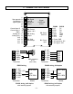
. TRANSMITTER FIELD WIRING Control input 2 Control input 1 GND Analog out Analog out + 1 2 3 4 5 6 1 2 3 1 2 AL2 AL2 AL1 AL1 1 2 3 4 See manuals for different signal types 6 5 4 3 2 1 TX RX NC GND BRX N/C Transmitter P6 Signal input & excitation output Signal conditioner board P5 Control inputs 1 & 2 P2 Serial data I/O P4 Analog output P3 Solid state relays 5 4 3 2 1 9 8 7 6 DB9 connector to PC (rear view) N/C ARX / ATX N/C GND BRX / BTX N/C Transmitter 6 5 4 3 2 1 RS485 N/C ARX ATX GND
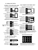
P6 - SIGNAL INPUT DETAIL PROCESS / TOTALIZER SIGNAL INPUT Single Powered Sensor Input DC & Externally Powered Process Excitation return + Excitation - Signal input + Signal input 1 2 3 4 -DC +DC 2-Wire Process Transmitter Excitation return + Excitation - Signal input + Signal input 1 2 3 4 DUAL CHANNEL PULSE SIGNAL INPUT ..
7. PROGRAMMING YOUR TRANSMITTER OVERVIEW Our transmitters are easily programmed using a PC with an RS232 port and Instrument Setup (IS) software, which provides a graphical user interface. The software allows uploading, editing, downloading and saving of setup data, execution of commands under computer control, listing, plotting and graphing of data, and computer prompted calibration. USING IS SOFTWARE Use a 3-wire RS232 cable (P/N CBL04) to connect your transmitter to the COM port of your PC.
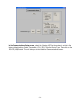
In the Communications Setup screen, select the Custom ASCII as the protocol, as this is the factory default setting. Select Transmitter LTA, LTM, LTS as the Device Type. Then click on the RS-232 (USB) button. This will take you to the Establish Communications screen.
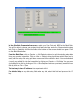
In the Establish Communications screen, select your Com Port and 9600 as the Baud Rate. You will be able to change your protocol and baud rate later under the Communication setup tab. Click on Establish, and the two fields at the bottom of the screen should turn green. Click on the Main Menu button. From the Main Menu, click on Counter => Get Setup to retrieve (or get) the existing setup data from your counter transmitter.
Click on Counter => Get Setup to retrieve the current setup information from your counter transmitter, then on View => Setup, which will take you to the Input+Display tab. Use this screen to set up Signal Input, Display, and Control Inputs. Click on the Scaling tab to scale your transmitter.
Click on the Filter tab to set to set up filtering for your readings. Click on the Relay Alarms tab to set up your transmitter’s two solid state relays, which are standard. Reminder: for detailed help on any data entry field under any tab, select that field and press on the F1 key.
Click on the Communication tab to view the communication parameters that you used to establish default communications with your transmitter. You can reselect Baud Rate, Device Address, Serial Protocol, and Full/Half Duplex, even though you may have selected different values to establish initial communications with your PC. Click on the Analog Out tab to scale your analog output, which is standard. Under Range, select 0-20 mA Current, 0-10V Voltage, or 4-20 mA.
ADDITIONAL FEATURES • The Commands pull-down menu allows you to execute certain functions by using your computer mouse. This menu will be grayed out unless a Get Setup has been executed. • The Readings pull-down menu provides three formats to display input data on your PC monitor. Use the Pause and Continue buttons to control the timing of data collection, then press Print for a hardcopy on your PC printer. - List presents the latest internal readings in a 20-row by 10-column table.
Graph • The Jumpers pull-down menu shows jumper positions for the selected signal conditioner boards and the main board, duplicating information in this manual.
8. OPENING YOUR TRANSMITTER CASE WHEN TO CHANGE JUMPERS Most users will never have the need to open the transmitter case. The transmitters are shipped fully jumpered and ready for scaling. The signal conditioner type, range and temperature sensor are specified by the model number on the transmitter label. To select a different signal conditioner range, you may open the transmitter case and change jumper settings. Your selected range should encompass your maximum expected signal levels.
9. DUAL CHANNEL PULSE OR AC INPUT SIGNAL CONDITIONER BOARD This signal conditioner board is used for the frequency, rate, period, timing, phase angle, or duty cycle functions. The board needs to be configured via jumpers for the input signal type and level. It is recognized by Instrument Setup software, which will bring up the applicable menu items for the Input Option “Dual Sig Cond.
Function Block Jumper Setting Frequency Response A0 & B0 b a Bias Resistor A1 & B1 a b Contact Debounce A4 & B4 b a, c c 1 MHz max 30 kHz max 250 Hz max 10 kOhm pull-up to 5V 10 kOhm pull-down to -5V None 3 msec 50 msec Common Jumper Settings Input Type Logic levels NPN open collector PNP open collector Contact closures Line frequency Turbine flow meter Vmax 250V NA NA NA 250V 250V A0 & B0 A1 & B1 A2 & B2 A3 & B3 A4 & B4 b b a or b b b a b a - a a a b a - b b b a, c a, c b RATE & FREQUENCY
• Rates A+B, A-B, AxB, A-B, A/B, A/B-1 (Extended counter) can output arithmetic combi- nations of Rates A and B (Item #1), Rate A (Item #2), or Rate B (Item #3). With rates A and B scaled to produce a ratio close to 1 and an offset of -1, the special combination A/B-1, called “Draw,” can output percentage changes, such as elongation of material as it passes between rollers. PERIOD MODES The inverse of frequency. Normally expressed in seconds.
together and selecting a positive or negative edge to start (Slope A) and the opposite polarity edge to stop (Slope B). If multiple start and stop pulses occur during the Gate Time, the displayed value is the average of pulse widths. The value is updated at the end of each Gate Time. With a scale factor of 1, one count is one microsecond. • Stopwatch A to A times individual events applied to Channel A (Item #1) and the accu- mulated “Grand Total Time” of all events since last reset (Item #2).
10. V-TO F CONVERTER SIGNAL CONDITIONER BOARD This process receiver signal conditioner board converts 0-1 mA, 4-20 mA or 0-10 V analog process signals to a frequency signal, which is then processed mathematically by the counter main board to produce an internal reading of rate, total (time x rate), or 1/rate (time based on rate). Square root extraction is selectable in software.
11. QUADRATURE SIGNAL CONDITIONER BOARD This signal conditioner can be used for quadrature position (Basic or Extended main board) or for quadrature position and rate (Extended main board). Two quadrature signals, which are 90º out of phase, are applied to the Channel A and B inputs. Their phase relationship determines whether the count is clockwise (+) or counterclockwise (-). A zero index signal may be applied to a Z Channel as a position reference.
Phase for Up Count E7 A positive, negative B transition (A leads B) A positive, positive B transition (B leads A) none a Count-by Options E9 X1 = positive edge of A input X2 = positive & negative edges of A input X4 = positive & negative edges of A & B inputs none a b Zero Index Polarity E8 Positive Negative c none Zero Index ANDing Zero Index (no ANDing) Zero Index AND /A Zero Index AND /B Zero Index AND A Zero Index AND B Zero Index AND /A AND /B Zero Index AND /A AND B Zero Index AND A AND /B
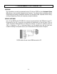
12. MAIN BOARD JUMPER SETTINGS d b a E6 c a E4 b E1 E3 E2 Serial Signal RS485 RS232 c b a a b d c Duplex Jumpers Termination Resistor* Full None E6 a = Transmit E6 c = Receive Half E6 b + d** E6 c Full None None * The termination resistor jumper settings should only be selected if the transmitter is the last device on an RS485 line longer than 200 feet (60 m). ** Or jumper external BTX to BRX and ATX to ARX (same effect as internal jumpers).
13. DUAL RELAY OPERATION The optional dual solid state relays can operate in a basic alarm mode, in a hysteresis band mode, or in a deviation band modes, as explained below. Setpoint operation is referenced to the digital reading in engineering units that is internal to the transmitter. For example, rate alarm or control would be referenced to a setpoint in RPM.
band is often used to minimize relay chatter. A wide hysteresis band can be used for on-off control applications. The hysteresis band equals two hysteresis limits. A deviation band controls relay action symmetrically around a setpoint. The relay actuates when the reading falls within the deviation band, and de-actuates when the reading falls outside. A limit (such as 50 counts) is set up around both sides of the setpoint to create the deviation band, which equals two limits.
Calibration of the quartz crystal is easily accomplished using Instrument Setup software. Select Calibration from the Main Menu. Apply a frequency reference signal, and enter the known frequency in Hz. Calibration of the V-to-F signal conditioner requires use of voltage reference signals and the calibration program vfcal3.exe, which is available for download. 16. CUSTOM CURVE LINEARIZATION Curve.
17. MODBUS PROTOCOL TRANSMITTER COMMUNICATIONS 1.0 GENERAL The Modbus capability conforms to the Modbus over Serial Line Specification & Implementation guide, V1.0. Both the Modbus RTU and Modbus ASCII protocols are implemented: Modbus RTU Baud Rate........... 300, 600, 1200, 2400, 4800, 9600 or 19200 Data Format ....... 1 start bit, 8 data bits, 1 parity bit, 1 stop bit (11 bits total) Parity.................. None, Odd, Even (if None, then 2 Stop bits for 11 total) Address..............
4.0 COMMUNICATIONS SETUP Parameters selectable via Instrument Setup software, distributed on CD ROM: Serial Protocol ...............................Custom ASCII, Modbus RTU, Modbus ASCII Modbus ASCII Gap Timeout...........1 sec, 3 sec, 5 sec, 10 sec Baud Rate.......................................300, 600, 1200, 2400, 4800, 9600, 19200 Parity .............................................No parity, odd parity, even parity Device Address .............................0 to 247 5.
FC08: Diagnostics Checks communications between the Master and Slave, and returns the count in the Modbus Slave counters (which are reset when the meter is reset). Hex Sub Function Code Data Send Response Data 00 00 Any Same as sent 00 01 Description Returns Query Data (N x 2 bytes). Echo Request. Restarts Communications. If in the Listen-Only mode, no response occurs. Takes Slave out of the Listen-Only mode and one of the following: Clears communications event counters.
6.0 SUPPORTED EXCEPTION RESPONSE CODES Code Name Error Description ---- -------------------- -----------------------------------------------------01 Illegal Function Illegal Function Code for this Slave. Only hex Function Codes 03, 04, 05, 08, 10 (dec 16) are allowed. 02 Illegal Data Address Illegal Register Address for this Slave. 03 Illegal Data Value Illegal data value or data length for the Modbus protocol. 04 Slave Device Failure Slave device failure (eg. Transmitter set for external gate). 7.
Modbus ASCII Format FC Action 03 03 Byte Number 1 2 3 Request Response : : MA MA FC FC RA RA NR NR LRC CR NB DD* DD* LRC CR LF LF 04 04 Request Response : : MA MA FC FC RA RA NR NR LRC CR NB DD* DD* LRC CR LF LF 05 05 Request Response : : MA MA FC FC RA RA RA WW WW LRC CR RA WW WW LRC CR LF LF 08 08 Request Response : : MA MA FC FC SF SF SF SF WW WW LRC CR DD DD LRC CR LF LF 10 10 Request Response : : MA MA FC FC RA RA RA RA NR NR : MA FC +80 EC LRC CR Excepti
18. CUSTOM ASCII PROTOCOL TRANSMITTER COMMUNICATIONS 1.0 SERIAL COMMUNICATION FORMAT The Custom ASCII serial communication format for both RS232 and RS485 is the following: Mode ................ Full Duplex (Separate transmit and receive lines) and Half Duplex (RS485 only) Baud Rate ......... 300, 600, 1200, 2400, 4800, 9600, 19200 selectable with Instrument Setup software. Parity ................ None Word length ...... 8 data bits Stop bit ............ 1 2.
Values are transmitted in a continuous string with no intervening spaces. If the 5th digit in is set to 1 using Instrument Setup software, the termination characters of and optional appear after each value. If the 5th digit is et to 0, the termination characters appear only once at the end of the string. In either case, if included, the coded character appears at the end of the last value only. 3.
Char # Character 1 2 3 4 * 0-V A-Z 0-U Description Command Identifier. Recognition Character. Device Address. 0 addresses all devices, 1-V specific devices. Command Function Sub-command. Number of Bytes of RAM or Words (2 Bytes) of non-volatile memory data being transferred. CHAR 2 - Address Codes A Serial Communications Address Code from 1 to V follows the “*” to indicate the device address number from 1 to 31.
Peak value reset Remote display reset Valley reset Tare function Tare reset 6.0 *1C3 *1C4 *1C9 *1CA *1CB READING AND WRITING TO RAM AND NONVOLATILE MEMORY CHAR 1, 2 The Recognition character and Meter Address Code are the same as shown in previous table.
General, Reading and Writing Ram Memory Data RAM memory data is read and written as a continuous string of bytes consisting of 2 hex characters (0-9,A-F) per byte. Included in the command are the total number of bytes to be transferred and the most significant address in RAM of the continuous string of bytes.
19. “CTR” TRANSMITTER SPECIFICATIONS Mechanical Case Dimensions .........................................................................................120 x 101 x 22.5 mm Case Mounting................................................................................ 35 mm DIN rail per EN 50022 Electrical Connections..............................................................Detachable screw plug connectors Environmental Operating Temperature ................................................................
DUAL CHANNEL SIGNAL CONDITIONER Crystal Accuracy at 25ºC....................................................................................................±2 ppm Crystal Tempco...................................................................................................±1 ppm/degree C Long-Term Drift of Crystal.........................................................................................±5 ppm/year Signal Types ....................
20. WARRANTY Laurel Electronics Inc. warrants its products against defects in materials or workmanship for a period of one year from the date of purchase. In the event of a defect during the warranty period, the unit should be returned, freight prepaid (and all duties and taxes) by the Buyer, to the authorized Laurel distributor where the unit was purchased. The distributor, at its option, will repair or replace the defective unit.