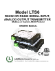
Model LTS6 RS232 OR RS485 SERIAL INPUT, ANALOG OUTPUT TRANSMITTER Modbus or Custom ASCII Protocol OWNERS MANUAL LAUREL Electronics Inc. 3183-G Airway Ave, Costa Mesa, CA, 92626, USA Tel: (714) 434-6131 Fax: (714) 434-3766 • Website: www.laurels.
1. ORDERING GUIDE, SERIAL INPUT TRANSMITTER Configure a model number in this format: LTS600, CBL04 LTS6…Transmitter with 4-20 mA, 0-20 mA or 0-10V isolated analog output, RS232 or RS485 serial data input, and dual 120 mA solid state relays. Default jumpered for RS232. LTSE6E… Transmitter with 4-20 mA, 0-20 mA or 0-10V isolated analog output, Ethernet serial data input, and dual 120 mA solid state relays. ACCESSORIES CBL04……RS232 cable, two 3-pin connectors on transmitter end, DB9 connector on computer end.
. INTRODUCTION, RS232 OR RS485 SERIAL INPUT TRANSMITTER The LTS6 serial input to analog output transmitter (or serial-to-analog converter) accepts RS232 or RS485 serial data using the Modbus or Custom ASCII protocol, and converts it to an isolated, scalable 4-20 mA, 0-20 mA or 0-10V analog output. The unit fits on a 35 mm DIN rail and is only 22.5 mm (0.89") thick. It is normally powered by AC (85-264 Vac), but can optionally be powered by low voltage AC or DC.
5. SAFETY CONSIDERATIONS Warning: Use of this transmitter in a manner other than specified may impair the protection of the device and subject the user to a hazard. Visually inspect the unit for signs of damage. If the unit is damaged, do not attempt to operate. Caution: • This unit may be powered with AC (mains) from 85-264 Vac or 90-300 Vdc with the high voltage power supply option, or 12-30 Vac or 10-48 Vdc with the low voltage power supply option.
6.
7. PROGRAMMING YOUR TRANSMITTER OVERVIEW Serial input transmitters are programmed using a PC with an RS232 port and Instrument Setup (IS) software, which provides a graphical user interface. The software allows uploading, editing, downloading and saving of setup data. CONNECTING TO YOUR PC Use a 3-wire RS232 cable (P/N CBL04) to connect your transmitter to the COM port of your PC. Download the file ISx_x_x.exe from our website and double-click on the file name.
as the Baud Rate. You will be able to change your protocol and baud rate later under the Communication setup tab. Click on Establish, and the two fields at the bottom of the screen should turn green and display your communication parameters and the counter-transmitter revision level. Click on Main Menu. The computer will remember your communication settings for the next time that you run IS software. The best way to learn IS software is to experiment with it.
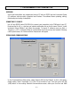
SETTING UP BASIC OPERATION Under the Input+Display tab, select 000.00 Secs for Time Out. Ignore Signal Input, Gate Time, Filter, and Power-On Total, as these parameters do not apply to the serial input transmitter. Under Display, select Remote A, Remote S or Remote C. These items correspond to the Remote A, Remote S and Remote C operating modes, which are explained under the “Custom ASCII Protocol Transmitter Communications” section of this manual.
SETTING UP RELAY ALARMS OPERATION Under the Relay Alarms tab, enter the Setpoint 1 and 2 values as well as other parameters applicable to relay operation. Set Alarm Source to Item 3 as illustrated. Please see the “Dual Relay Operation” section of this manual for an explanation of the relay operating modes.
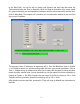
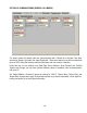
SETTING UP COMMUNICATIONS (REMOTE A & S MODES) The above screen will appear under the Communication tab if Remote A or Remote S has been selected as Display Type under the Input+Display tab. These two modes are not able to extract data from an ASCII string that contains multiple data values and non-numeric characters.
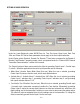
SETTING UP COMMUNICATIONS (REMOTE C MODE) The above screen will appear under the Communication tab if Remote C has been selected as Display Type under the Input+Display tab. This mode is able to extract data from an ASCII string that contains multiple data values and nonnumeric characters. Please see the F1 Help screen to the right.
SETTING UP THE ANALOG OUTPUT Under the Analog Out tab, set Source to Item 3. Under Range, select 0-20 mA Current, 0-10V Voltage, or 4-20 mA Current as your desired analog output. Type in your Lo Range Reading and Hi Range reading. These will create the two endpoint values of your analog output range.
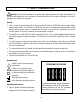
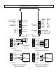
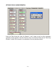
8. CHANGING JUMPER SETTINGS d b a E6 c a E4 b E1 E3 E2 c b a a b d c Jumpers at E6 are used to set the input signal to RS232 or RS485. The factory default setting is RS232, which allows direct connection to a PC. As an alternative to using jumpers, the selection of half-duplex RS485 can also be achieved by externally connecting BTX to BRX and ATX to ARX. A termination resistor can be selected if the transmitter is the last device on an RS485 line longer than 200 feet (60 m).
WHEN TO CHANGE JUMPERS Most users will never have the need to open the transmitter case. Our transmitters are shipped fully jumpered and ready for scaling. The transmitter type is specified by the model number on the transmitter label. The selection serial signal (RS232 or RS485) can be achieved by jumpers on the main board or by external wiring, as documented on the previous page. The factory default setting for the serial signal level is RS232.
9. DUAL RELAY OPERATION The optional dual solid state relays can operate in a basic alarm mode, in a hysteresis band mode, or in a deviation band mode, as explained below. Setpoint operation is referenced to the digital reading that is received as serial data. For example, temperature alarm or control would be referenced to a setpoint in °C or °F.
A deviation band alarm controls relay action symmetrically around a setpoint. The relay actuates when the reading falls within the deviation band, and de-actuates when the reading falls outside. A deviation value (such as 50 counts) is set up around both sides of the setpoint to create the deviation band. Passbands around a setpoint are often used for component testing.
10. MODBUS PROTOCOL TRANSMITTER COMMUNICATIONS 1. GENERAL The Modbus capability conforms to the Modbus over Serial Line Specification & Implementation guide, V1.0. Both the Modbus RTU and Modbus ASCII protocols are implemented: Modbus RTU Baud Rate........... 300, 600, 1200, 2400, 4800, 9600 or 19200 Data Format ....... 1 start bit, 8 data bits, 1 parity bit, 1 stop bit (11 bits total) Parity.................. None, Odd, Even (if None, then 2 Stop bits for 11 total) Address..............
4. COMMUNICATIONS SETUP Parameters selectable via Instrument Setup software, distributed on CD ROM: Serial Protocol ...............................Custom ASCII, Modbus RTU, Modbus ASCII Modbus ASCII Gap Timeout...........1 sec, 3 sec, 5 sec, 10 sec Baud Rate.......................................300, 600, 1200, 2400, 4800, 9600, 19200 Parity .............................................No parity, odd parity, even parity Device Address .............................0 to 247 5.
Modbus ASCII Format FC Action 05 05 10 10 Byte Number 1 2 3 4 5 6 Request Response : : MA MA FC FC RA RA RA RA WW WW LRC WW WW LRC Request Response : : MA MA FC FC RA RA RA RA NR NR - 19-- 7 NR NR 8 9 10 CR CR LF LF 11 NB DD* DD* LRC LRC CR LF 12 13 CR LF
11. CUSTOM ASCII PROTOCOL TRANSMITTER COMMUNICATIONS All setup parameters are entered into the transmitter via Instrument Setup (IS) software, including the serial communication format, digital address, operating mode, analog output scaling, and relay operating modes and setpoints. 1. SERIAL COMMUNICATION FORMAT The Custom ASCII serial communication format for both RS232 and RS485 is the following: Modes...............Full Duplex (separate transmit and receive lines) or Half Duplex (RS485 only). Baud Rate .
Remote A is an addressable input mode that uses the K command letter. It can convert remote data on one or more transmitters having the command address in a multi-point configuration or a single transmitter having the command address in a point-to-point configuration. Remote S is not addressable, and data representing a value to be retransmitted as an analog output is received via a point-to-point connection. The value is stored where it may be selected for Alarm comparisons.
. A = Decimal point (optional). = Alarm Character (optional). A = no alarms, B = alarm 1 active, C = alarm 2 active, D = alarms 1 & 2 active. = Carriage return character Remote S Data Format: SDDDDDD.A S D . A = = = = Sign of value (optional), space (or +) for positive, - for negative value. Data. Number of digits can be 1-6. Decimal point (optional). Alarm Character (optional). A = no alarms, B = alarm 1 active, C = alarm 2 active, D = alarms 1 & 2 active.
12. SPECIFICATIONS, SERIAL INPUT TRANSMITTER Serial Data Input Signal Levels...................................... RS232, full-duplex RS485, half-duplex RS485 (selectable) Protocol ................................. Modbus RTU, Modbus ASCII, Custom ASCII (software selectable) Serial Connector ........................................................................ Detachable dual 3-position plugs Analog Output (standard) Output Levels...........................................................................
13. WARRANTY Laurel Electronics Inc. warrants its products against defects in materials or workmanship for a period of one year from the date of purchase. In the event of a defect during the warranty period, the unit should be returned, freight prepaid (and all duties and taxes) by the Buyer, to the authorized Laurel distributor where the unit was purchased. The distributor, at its option, will repair or replace the defective unit.