Modbus Protocol COMMUNICATIONS MANUAL For Series 2 Laureate Digital Panel Meters, Counters, Timers & DIN-Rail Transmitters Now with Ethernet LAUREL Electronics Inc. 3183-G Airway Ave, Costa Mesa, CA, 92626, USA Tel: (714) 434-6131 Fax: (714) 434-3766 Website: www.laurels.
1. TABLE OF CONTENTS 1. TABLE OF CONTENTS ....................................................................................................... 2 2. INTRODUCTION, MODBUS PROTOCOL ............................................................................ 3 3. MODBUS CONNECTION EXAMPLES ................................................................................. 4 4. JUMPER SETTINGS & FIELD WIRING .............................................................................. 5 5.
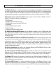
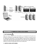
2. INTRODUCTION, MODBUS PROTOCOL The Modbus Protocol is an industry-standard communications protocol that is selectable with all our serial communications signal options: Ethernet, USB, RS485 and RS232. It is implemented by the microcomputer on the main board and is compliant with Modbus RTU or ASCII transmission modes (software selectable), as specified in Modbus over Serial Line Specification V1.0 (2002). Digital panel meters, counters and timers require a plug-in option board for Modbus communications.
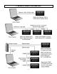
3.
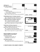
4. JUMPER SETTINGS & FIELD WIRING 1. SAFETY WARNINGS Digital panel meters, counters, timers and transmitters may be powered with AC (mains) from 85-264 Vac or 95-300 Vdc with standard high voltage power, or 12-34V ac or 10-48 Vdc with the low voltage power supply option. To avoid the possibility of electrical shock or damaging short circuits, always unplug the device before opening the case. Please refer to the respective device manuals for full safety information and instruction on how to open the case.
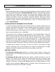
USB Board & Basic Ethernet Board No jumpers needed. RS232 Board e - Normal operation. f - Slave display to RS232 from another meter. g - Pull-up resistor on RTS line. Note: Board is shipped with jumpers e and g installed RS485-Modbus Board, Full Duplex Operation b & e - Bias jumpers should be installed on 1 board. a & d - Installed on last meter in long cable run. RS485-Modbus Board, Half Duplex Operation b & e - bias jumpers installed on 1 board. c & f - installed for half duplex operation.
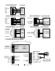
RS232 INTERFACE N/C ISO GND RX TX RTS N/C Computer 6 5 4 3 2 1 GND TX RX RTS RS485 INTERFACE - FULL DUPLEX ISO GND BRX ARX ATX BTX ISO GND RS485 INTERFACE - HALF DUPLEX ISO GND GND BTX ATX ARX BRX GND 6 5 4 3 2 1 ATX / ARX BTX / BRX ISO GND RS485-MODBUS - FULL DUPLEX (A') RXD0 (B') RXD1 + (B) TXD1 * (A) TXD0 ISO GND ATX / ARX BTX / BRX GND RS485-MODBUS - HALF DUPLEX TXD0 TXD1 1 2 3 4 5 6 7 8 GND 6 5 4 3 2 1 RXD1 RXD0 (B) TX / RXD1 (A) TX / RXD0 GND ISO GND 1 2 3 4 5 6 7 8 (B) TX/RXD1 (A
d a E4 b E1 E3 E2 Serial Signal * The termination resistor jumper settings should only be selected if the transmitter is the last device on an RS485 line longer than 200 feet (60 m). b a E6 c ** Or jumper external BTX to BRX and ATX to ARX (same effect as internal jumpers).
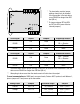
5. PROGRAMMING YOUR MODBUS DEVICE OVERVIEW Modbus digital panel meters, counters, timers and transmitters are easily programmed via their serial port using Windows-based Instrument Setup (IS) software, which provides a graphical user interface and is available at no charge. This software allows uploading, editing, downloading and saving of setup data, execution of commands under computer control, listing, plotting and graphing of data, and computer prompted calibration.
6. MODBUS PROTOCOL IMPLEMENTATION 1. GENERAL The Modbus capability conforms to the Modbus over Serial Line Specification & Implementation guide, V1.0. Both the Modbus RTU and Modbus ASCII protocols are implemented: Modbus RTU Baud Rate........... .............................................. 300, 600, 1200, 2400, 4800, 9600 or 19200 Data Format ....... ........................1 start bit, 8 data bits, 1 parity bit, 1 stop bit (11 bits total) Parity.................. .............................
4. PARAMETERS SELECTABLE VIA INSTRUMENT SETUP (IS) SOFTWARE Serial Protocol ..................................................Custom ASCII, Modbus RTU, Modbus ASCII Modbus ASCII Gap Timeout.......................................................... 1 sec, 3 sec, 5 sec, 10 sec Baud Rate..............................................................300, 600, 1200, 2400, 4800, 9600, 19200 Parity ...............................No parity, 2 stop bits; odd parity,1 stop bit; even parity, 1 stop bit Device Address .
FC04: Read Input Registers Reads measurement values and alarm status. Returns values in M31 or 2C32 format without decimal point (see Sec 11, p 16). The displayed system decimal point can be read with FC03 at addr 0057. Use only high word Starting Register Addresses and an even number of Registers. Register Address Meter or Analog Input Transmitter Response (M31 format) Base 1 Base 0 Std addr. PLC addr.
FC08: Diagnostics Checks communications between the Master and Slave, and returns the count in the Modbus Slave counters (which are reset when the meter is reset). Hex Sub Function Code Data Sent Response Data 00 00 Any Same Returns Query Data (N x 2 bytes). Echo Request. FF 00 00 00 FF 00 00 00 Restarts Communications. If in the Listen-Only mode, no response occurs. Takes Slave out of the ListenOnly mode and one of the following: — Clears communications event counters.
8. SUPPORTED EXCEPTION RESPONSE CODES Code Name Error Description 01 Illegal Function Illegal Function Code for this Slave. Only hex Function Codes 03, 04, 05, 08, 10 (dec 16) are allowed. 02 Illegal Data Address Illegal Register Address for this Slave and/or Register Length. 03 Illegal Data Value Illegal data value or data length for the Modbus protocol. 04 Slave Device Failure Slave device failure (eg. Device set for external gate). 9.
FC Action 03 03 Column Number 1 2 3 Request Response : : MA MA FC FC RA RA NR NR LRC CR NB DD* DD* LRC CR LF LF 04 04 Request Response : : MA MA FC FC RA RA NR NR LRC CR NB DD* DD* LRC CR LF LF 05 05 Request Response : : MA MA FC FC RA RA RA WW WW LRC CR RA WW WW LRC CR LF LF 08 08 Request Response : : MA MA FC FC SF SF SF WW WW LRC CR SF DD* DD* LRC CR LF LF 10 10 Request Response : : MA MA FC FC RA RA RA RA : MA FC +80 EC LRC CR Exception Response 4 5 6 NR
Because the Counter/Timer can provide up to 3 display items during normal operation, it can be used to provide additional features when used as a Remote Display. It is possible to send Remote Data to Item 3 using addresses 006B,C or 006D,E. If the Counter/Timer is set up with the "Source" menu item set to Item 3, it will make alarm comparisons to its Setpoints using the Remote Data.
12. B16 Bit Significance M16 Binary Magnitude M15 Sign + Binary Magnitude Hi Byte 0000 0000 Hi Byte Lo Byte . XXXX XXXX XXXX XXXX Hi Byte Lo Byte . SXXX XXXX XXXX XXXX Lo Byte . BBBB BBBB 7654 3210 METER & ANALOG INPUT TRANSMITTER INTERNAL REGISTER ADDRESSES Data Types - as shown: FC03 READ and FC10 (dec16) WRITE Use high word starting Register Addresses and an even number of Registers.
40 41 42 43 44 0028 0029 002A 002B 002C Deviation 4 (Lo word) (not for Scale Meter) Analog Lo (Hi word) 2C32 Analog Lo (Lo word) Analog Hi (Hi word) 2C32 Analog Hi (Lo word) as displayed Dec pt same as displayed Dec pt same as displayed * Values are for Base 1 Standard addressing. Add 1 for Base 0 PLC addressing. ** Scale = .0001 x dec value of (Hi word + Lo word) Data Type B16 For the following, use any starting Register Address and any number of Registers.
69 0045 Input Type 70 0046 Setup (applicable to DPM) M = Meter F = Function D = Display Lo Byte Hex value 40-4D Thermocouple JF, C, KF, KC, NF, NC, EF, EC, TF, TC, SF, SC, RF, RC 50-5C RTD pre-2009: 4-wire DIN°F, 4-wire DIN°C, 4-wire ANSI°F, 4-wire°C, 3-wire DIN°F, 3-wire DIN°C, 3-wire ANSI°F, 3-wire ANSI°C, 2-wire DIN°F, 2-wire DIN°C, 2-wire ANSI°F, 2-wire ANSI°C, Short 50-57 RTD post-2009: DIN°F, DIN°C, ANSI°F, ANSI°C, Ni°F, Ni°C, Cu°F, Cu°C, 60-64 DC 0.
70 0046 Setup (applicable to Scale Meter) M = Meter F = Function D = Display T = Tare 71 0047 Filter 72 73 0048 0049 Options Serial Config 1 Bits 3:0 Ctrl In 1 Ctrl In 2 Both Reset Hex 0 M Reset M Hold M Reset Hex 1 F Reset Peak D M Reset Hex 2 M Hold Peak D F Reset Hex 3 M Hold Tare Tare Hex 4 Peak Tare F Reset Hex 5 M Reset Tare M Reset Hex 6 F Reset Tare M Reset Hex 7 T Reset Tare M Reset Hex 8 D Blank Tare M Reset Hex 9 M Reset D Blank M Reset Hex A F Reset D Blank M Reset Hex B D Item Tare Tar
74 004A Serial Config 2 75 004B Serial Config 3 76 004C Serial Config 4 77 004D Config (applicable to DPM) 77 004D Config (applicable to Scale Meter) Bits 4:0 Meter Serial Address (0-31) [Non-Modbus] Hex 0 = Broadcast (01 = 1 to 0A = 10), 0F = 15, 10 = 16, 1F = 31 Bit 5 0 = Continuous Mode, 1 = Command Mode Bit 6 0 = No Alarm data with readings, 1 = Alarm data Bit 7 0 = No LF following CR, 1 = LF following CR Bits 2:0 for DPM.
78 78 004E 004E Lockout 1 (applicable to DPM) Lockout 1 (applicable to Scale Meter) 79 004F Lockout 2 81 0051 Setup 1 (not for Scale Meter) 81 0051 Count (applies to Scale Meter) Bit 0 Bit 2 Bit 4 Bit 0 Bit 2 Bit 4 Bit 6 Bit 0 Bit 1 Bit 2 Bit 3 Bit 4 Bit 5 Bit 6 Bits 1:0 Bits 3:0 Bits 6:4 82 0052 Analog Output Setup (applies to DPM) Bit 0 Bit 1 Bits 2:1 82 0052 Analog Output Setup (applies to Scale Meter) Bit 0 Bit 1 Bits 3:2 87 0057 System Decimal Point Bits 2:0 93 94 95 005D
READ ONLY (FC03) – Data Type B16 100 0064 Analog Output DAC Type 101 0065 Device Type 102 103 104 0066 0067 0068 Revision Overload Value Signal Conditioner Type Bits 7:0 0 = none, 1 = 1 output, unipolar (12-bit, pre 2009) 2 = 1 output, unipolar (16-bit, pre 2009) 3 = 1 output, uni or bipolar (16-bit, post 2009) 4 = 2 outputs, unipolar (16-bit, post 2009, not for Scale Meter) Bits 7:0 01 = DPM meter 02 = Scale meter 03 = Counter/timer met.
10 11 12 13 14 15 16 17 18 19 20 21 22 23 24 25 26 27 28 29 30 31 32 33 34 35 36 37 38 39 40 41 42 43 44 45 46 47 48 000A 000B 000C 000D 000E 000F 0010 0011 0012 0013 0014 0015 0016 0017 0018 0019 001A 001B 001C 001D 001E 001F 0020 0021 0022 0023 0024 0025 0026 0027 0028 0029 002A 002B 002C 002D 002E 002F 0030 Scale 1Y (Lo word) Offset 1 (Hi word) Offset 1 (Lo word) Scale 2Y (Hi word) Scale 2Y (Lo word) Offset 2 (Hi word) Offset 2 (Lo word) Lo In 1 (Hi word) Lo In 1 (Lo word) Lo Rd 1 (Hi word) Lo Rd 1 (Lo
For the following, use any starting Register Addresses and any number of Registers. Register Addr Dec Hex 49 0031 0032 50 51 0033 52 0034 0035 53 54 0036 55 0037 56 0038 57 0039 58 003A 50 003B Data Type M16 M16 M16 M48 M48 M48 M48 M48 M48 M16 M15 Register Name GateTime TimeOut Pulses Total B (Hi word) Total B (Mid word) Total B (Lo word) Total A (Hi word) Total A (Mid word) Total A (Lo word) Cutoff Calibration Scaling & Decimal Point 1-19999 (4E1F) Dec Pt =XXX.XX 1-19999 (4E1F) Dec Pt =XX.
68 0044 69 0045 Input Type 70 0046 Bit 6 0 = Relay3 Active On 1 = Off Bit 7 0 = Relay4 Active On 1 = Off Alarm Bits 2:0 = # Readings before Alarms 3 & 4.
Hex 5 Hex 6 Hex 7 Hex 8 Hex 9 Hex A Hex B Hex C Hex D Hex E Hex F Hex F Bit 4 71 0047 Filter 72 73 0048 0049 Options Serial Config 1 Valley Peak FRest Function Reset External Gate MReset Meter Hold Peak or Valley FReset Reset Total A Reset Total B FReset Force Alarm1 Force Alarm2 No Action Meter Reset Display Blank MReset Function Reset Display Blank MReset Meter Hold Display Blank MReset Peak or Valley Display Blank FReset Display Blank External Gate MReset Item2 Item3 Item 1 = Neither/Both Tare Ena
74 75 004A 004B Serial Config 2 Serial Config 3 Bits 4:0 Bit 5 Bit 6 Bit 7 Bits 2:0 Bit 3 Bit 4 Bit 5 Bit 6 76 004C Serial Config 4 Bit 7 Bits 1:0 Bits 3:2 Bits 5:4 77 004D Config Bit 0 Bit 1 Bits 3:2 Bits 7:4 Meter Serial Address (0-31) [Non-Modbus] Hex 0 = Broadcast (01 = 1 to 0A = 10), 0F = 15, 10 = 16, 1F = 31 0 = Continuous Mode, 1 = Command Mode 0 = No Alarm data w/ readings, 1 = Alarm data 0 = No LF following CR, 1 = LF following CR Data sent in serial output 0 = All active Items,
78 004E Lockout 1 79 004F Lockout 2 80 50 Batch Operation 7 = Remote Display, Value 8 = 1st Value in String 9 = 2nd Value in String A = 3rd Value in String B = 4th Value in String C = Remote Display using Start, Stop, Skip, Show Characters 0 = Enabled, 1 = Locked out Bit 0 Filter Bit 1 Gate Time, Timeout, Batch, Preset, Pulses, Cutoff Bit 2 Setup, Config, Display Number Bit 3 Input Type Bit 4 Setpoint Programming Bit 5 Alarm Config, Deviation / Hysteresis Bit 6 Scale, Offset, Resolution, 2 Coordina
81 0051 Alarm Source Bits 1:0 Bits 3:2 Bits 5:4 Bits 7:6 82 0052 83 0053 Analog Out Setup Scale Multiplier Bits1:0 Bit 2 Bits 3:0 Bits 7:4 84 0054 Trigger Slope Bit 0 Bit 1 85 0055 Display Item Bits 1:0 Bits 3:2 86 0056 Resolution Bits 3:0 87 0057 System Decimal Point Bits 3:0 Bits 7:4 Setpoint 2 Setpoint 1 Setpoint 4 Setpoint 3 For each Setpoint: 00 = Filtered Item, 01 = Item1, 10 = Item2, 11 = Item3 0 = Filtered Item, 1 = Item1, 2 = Item2, 3 = Item3 0 = Current Output, 1 = Voltage
READ ONLY (FC03) – Data Type B16 100 0064 Analog Output DAC Type 101 0065 Device Type 102 0066 Revision 0 = none, 1 = 1 output, unipolar (12-bit, pre 2009) 2 = 1 output, unipolar (16-bit, pre 2009) 3 = 1 output, uni or bipolar (16-bit, post 2009) 4 = 2 outputs, unipolar (16-bit, post 2009) Bits 7:0 01 = DPM meter 03 = Counter/Timer meter 05 = DPM transmitter 07 = Counter/Timer transmitter Bits 7:0 Hex value of Decimal Revision number WRITE ONLY FC10 (dec16) – Data Type 2C32 105 106 107 108 109 110
7. WARRANTY Laurel Electronics Inc. warrants its products against defects in materials or workmanship for a period of one year from the date of purchase. In the event of a defect during the warranty period, the unit should be returned, freight prepaid (and all duties and taxes) by the Buyer, to the authorized Laurel distributor where the unit was purchased. The distributor, at its option, will repair or replace the defective unit.