QLS Quad Output 4-20 mA Current Loop Splitter / Retransmitter With common mode isolation between input & outputs LAUREL Electronics Inc. 3183-G Airway Ave, Costa Mesa, CA, 92626, USA Tel: (714) 434-6131 Fax: (714) 434-3766 Website: www.laurels.
1. ORDERING GUIDE QLS-1 Quad isolated output loop splitter/ retransmitter, 85-264 Vac power. QLS-2 Quad isolated output loop splitter/ retransmitter, 10-48 Vdc or 12-32 Vac power. 3. PRODUCT DESCRIPTION Model QLS sources up to four (4) independently adjustable 4-20 mA outputs from a single input, which can be 4-20 mA, 1-5V, 0-5V or 0-10V, as selected by jumpers. The outputs can share a common ground.
5. SAFETY CONSIDERATIONS Warning: Use of this unit in a manner other than specified in this manual may impair the protection of the unit and subject the user to a hazard. Do not attempt to operate if the unit shows visible damage. Cautions: This unit may be powered from 85-264 Vac with the worldwide voltage power supply (Model QLS-1) or from 12-30 Vac or 10-48 Vdc (Model QLS-2). Verify that you have the proper model for the power to be used.
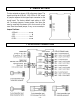
6. JUMPER SETTINGS The four outputs are always 4-20 mA process loops. The signal input can be 4-20 mA, 1-5V, 0-5V or 0-10V, as set by jumpers adjacent to the signal input connector on the circuit board. The factory default input setting is 4-20 mA. To change jumpers, remove power, then open the case by removing the screws at the four corners of the case. Store the unused jumper, if any, on an unused pin. Jumper Positions: 4-20 mA ............................a + c 1-5V .......................................
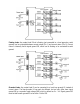
Floating loads: Any output load R that is floating (not connected to a local ground or earth ground) can be connected between current output (Pin 1) and current return (Pin 2). Current return is internally tied to signal ground SG, which can be floating or be connected to earth ground. Grounded loads: Any output load R can be connected to a local loop ground LG instead of current return.
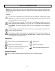
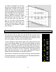
If a load R is grounded to a local loop ground LG, the available common mode voltage CMV is limited on the positive side by the unit’s internal power supply and on the negative side by the 600 mW power dissipation limit of an output transistor. The diagram to the right shows allowable CMV as a function of output load resistance R. For example, with a 250 ohm load, CMV can range from -13V to +17V. With a 500 ohm load, CMV can range from -18V to +12V.
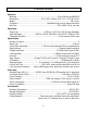
9. SPECIFICATIONS Mechanical Mounting ........................................................................................ 35 mm DIN rail per EN50 022 Dimensions.................................................. 22.5 x 103 x 128 mm (0.9” x 4.1” x 5.0”) W x H x D Weight ....................................................................................................................... 140 g (5 oz) Connectors ..............................................................
10. WARRANTY Laurel Electronics Inc. warrants its products against defects in materials or workmanship for a period of one year from the date of purchase. In the event of a defect during the warranty period, the unit should be returned, freight prepaid (and all duties and taxes) by the Buyer, to the authorized Laurel distributor where the unit was purchased. The distributor, at its option, will repair or replace the defective unit.