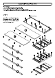
Dresser IMPORTANT Carefully remove all the parts from the carton and place them individually on a soft cloth to prevent scratches or other damage. Carefully and strictly follow these assembly instructions to ensure a completed product as designed. Do not use power tools above 8 volts to assemble. kL w, Sack Pansy 1pc. Part List E. Front Rail 1pe P F. Front All Front Rail 1 pe. 3 pes. Jo Back Panel Drawer Front Drawer SIDS L5. 4 pes. apes. K5 Drawer Bottom Drawer Bosom & pes. / 2 pes.
( Assembly Instructions 2/12 ) IMPORTANT » Use 3 soft cloth between these parts and the floor. = Do not use prows too's above 8 volts to assemble. » Do not tighten al! the screws until sate part s properly assembled. = The unit must be svelte to work properly. Use the included adjustable levelers to level. STEP 1 $4 Cam Lock Resew ! | Insert Cam Lock Screws into the per-drilied holes of Top (A), Side Panels (B}, {C), Front Rails {F), (G} and Back Panels {J1.
( Assembly Instructions 3/12 ) STEP 2 Assemble Back Panels and {J) with Cam Locks. (See Figure 1) 1 174" Round Head Screw STEP 3 Attach Front Rails {E} and (P} to Divider {D) with Cam Locks. Attach Front Rail (G) to Divider (D} with 11/4" Round Head Screw.
( Assembly Instructions 4/12 ) STEP 4 Attach unit from Step 2 to unit from Step 3 with Wooden Dowels and 1 1/4" Round Head Screws. STEP 5 Attach unit to Side Pane! {B) with Cam Locks.
( Assembly Instructions 5/12 ) STEP 6 Attach Side Pane! {C) to unit with Cam Locks. STEP Attach Bot torn {H) to unit with Wooden Dowels, Cam Locks and 1 174" Round Head Screws.
( Assembly Instructions 6/12 ) STEP 8 Attach Top {A) to unit with Wooden Dowels, Cam Locks and 1 3/4" Round Head Screws. Note: A Philips screwdriver 5" or less in length is recommended. To level the unit, adjust the adjustable levelers on the bottom of the legs. {See Figure 2} Wonder Dowel Note: Unit must be level to work properly.
( Assembly Instructions 7/12 ) IMPORTANT » Ta help reduce the risk of the unit tipping over, the Tip aver Restraint must be install STEP 9 Place unit at desired location. Mark wall with pencil just above and in-sine with hole in Top {A). {See Figure 3) Move unit. Drill a 3/8" hole in wall 1 1/2” below mark. Insert Anchor into the wall hole and attach Tip over Restraint to Anchor with 1 1/2” Round Head Screw and Flat Washer.
( Assembly Instructions 8/12 ) Drawer (K) STEP 10 Attach Drawer Sides (K3}, (K4) and Drawer Supports (K6} to Drawer Back {K2) with 11/4" Flat Head Screws. Roller at back . "yt 1 1/4" Fiat Head Resew 11/4" Fist Head Screw ——pa, STEP 11 Insert Drawer Bottom (K5} into the groove. Attach Drawer Front (K1} to unit with 11/4" Flat Head Screws. STEP 12 Attach Knobs with Machine Screws. Note: Drawer assembly is not complete until 3/4” Flat Head Screws are used in a later step.
( Assembly Instructions 9/12 ) Drawer (L) STEP 13 Attach Drawer Sides (K3}, (K4) and Drawer Supports (K6} to Drawer Back {K2) with 11/4” Flat Head Screws. Roller at back . "yt 1 1/4" Fiat Head Resew 114" Fist Head Screw ——pa, STEP 14 Insert Drawer Bottom (L5} into the groove. Attach Drawer Front (K1} to unit with 1 1/4" Flat Head Screws. STEP 15 Attach Knobs with Machine Screws. Note: Drawer assembly is not complete until 3/4” Flat Head Screws are used 'n a later step.
( Assembly Instructions 10/12 ) Drawer (M) STEP 16 Attach Drawer Sides (M3}, {M4} and Drawer Supports (K6} to Drawer Back (M2} with Rioter at bk 1 1/4" Flat Head Screws. STEP 17 Insert Drawer Bottom (L5} into the groove. Attach Drawer Front (M1} to unit with 1 1/4" Flat Head Screws. STEP 18 Attach Handle with Machine Screws. Aching Screw Note: Drawer assembly is not complete until 3/4” Flat Head Screws are used 'n a later step.
( Assembly Instructions 11/12 ) STEP 19 Loosen slightly the screws per-installed on the back of the drawer fronts. o -flB‘ -gkO = &A chiffon chiffon STEP 20 Insert the drawers into the unit, then adjust the drawer front panels left or right and up or down until the drawer gaps look proportional. STEP 21 Pull each drawer open slowly and re-tighten the screws from Step 19. Make sure the front panel does not move and lock the drawer front panel into position with 3/4" Flat Head Screws.
CARE INSTRUCTIONS NEVER allow liquids to remain on fumigate, Absorption causes parts to warp and split and finishes to determinate. NEVER use glass cleanest on finished furniture. Ammonia chemically attacks the finish.