
Installation Guide


LMW - Colony Collection Owner’s Manual
Rough in the wiring on a single 120VAC, 20 amp, GFCI protected dedicated circuit for each accessory installed
on the tub.
WARNINGS:
1) All electrical connections must be made by a licensed certified electrician in accordance with the
requirements of the National Electrical Code and applicable state and local codes and procedures.
2) All circuits connected to this unit must be equipped with Ground Fault Circuit Interrupter (GFCI)
protection. It is the tub installer’s responsibility to wire the circuit with GFCI.
3) All bathtubs equipped with an inline heater require two dedicated circuits. One for the whirlpool system
and one for optional inline heater.
4) DO NOT splice a longer cord to the power supply cord and DO NOT connect to an extension cord.
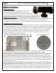
All whirlpool, air systems, and heaters are equipped with a molded plug on the end of a power supply core.
Install a separate, dedicated 120VAC, 20 Amp GFCI protected electrical wall plug outlet inside the access panel
for each accessory equipped on the tub. For example, if the tub is equipped with a whirlpool system only,
then one GFCI wall plug outlet is necessary. If the tub is equipped with both whirlpool system and a heater
then two separate circuits with GFCI wall plug outlets are required. Be sure to count the number of
accessories before installing the GFCI wall outlets. Also, the power supply cords equipped with each accessory
are only 2.5’ long so locate the GFCI wall outlet within 1.5’ of the intended accessory.
Electrical Requirements
.75 hp Pump – 120V, 7.5 Amps
Whirlpool heater – 120V, 12.0 Amps
2 hp Pump – 120V, 9.5 Amps
Air / Soaker heater – 120V, 12.5 Amps
2.5 hp Pump – 120V, 13.5 Amps
Air / Soaker heater – 240V, 16.0 Amps
2 hp Blower/Heater – 120V, 12.0 Amps
Ozonator – 120V, 1.0 Amps
Please note, that when sizing the electrical circuits to power the unit, you should always check the rating
labels on equipment because there could be changes.
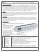
Install fill valves and spout in the desired locations. Note, due to various possible fill valve and spout locations,
the holes are not drilled at the factory. Make certain that the spout is long enough to clear the interior rim of
the tub. If installing fill valves on the deck of the tub, be sure that you have enough clearance for connections
of valve to tub and water connections before drilling/cutting into tub. Seal the joints under the tub rim and
against the wall with a water resistant seal. Then install a standard 1.5” trap to the drain and overflow.
Before proceeding, make a final operational check by filling the tub with water to the overflow and operate for
at least 5 minutes. Leave the water in the bath for 30 minutes, check the connections for leaks during and
after operation. Complete the installation with desired trim material on the back wall, side walls, and down
exposed interior walls.