
Installation Guide


Installation Instructions
Shower Stalls/Tub-Showers
laurelmountainbath.com • 800.930.0050
— 1 —
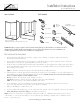
3/16” Drill Bit
3-1/2” Drill Bit
1” Drill Bit
Screw Driver Bit
#8 X 1”
Pan Head
Screws
100% Mildew
Resistant Silicone Sealant
LevelHammer
Tape Measure
Drill
Shower or Tub-Shower
Product illustration may not be representative of your unit.
Items Included Tools Needed
IMPORTANT! Upon receipt, inspect the unit for fit, finish and any damage or defect. Under no circumstances should a
damaged unit be installed. Neither Laurel Mountain or Lowe’s will be responsible for removal or reinstallation costs
should a replacement be necessary due to installation of a damaged unit.
PRE-INSTALLATION PLANNING
1. Unit must be placed within bathroom area before completion of door framing or, if preferred, studs may be omitted or
knocked-out to permit unit placement.
2. Review job print and Laurel Mountain rough-in dimensions; verify all key dimensions against actual job conditions . Make sure
framed-in alcove is of proper size, square and plumb; check floor for levelness.
3. The blocks and/or legs attached underneath the bottom of the bath fixture are an integral part of the support system and should not
be removed. Although these blocks and/or legs need not touch for an acceptable install, this may be an indication that the unit
and/or sub-floor are out of level.
NOTE: No foundation materials are required on Laurel Mountain Shower and Tub/Shower units.
4. If fire-rated alcove is required, approved finish material must be in place prior to unit installation to meet fire safety requirements
of local building code and/or FHA/HUD Minimum Property Standards.
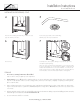
NOTE: Finished alcove must have interior dimensions
shown on rough-in diagram to permit installation of unit.
5. Showers: Provide 6” floor opening for 2” IPS and drain connection.
Tub-Showers: Provide 6 x 12 floor opening for 1
1
⁄2
” drain, waste and overflow (DWO) kit.
NOTE: Be sure floor opening location matches bath fixture drain location.
6. To avoid obstruction, make sure that supply lines and valve plumbing are not strapped to studs and do not project into
alcove. Also, drain pipe must not project above floor level prior to installation.
7. Make sure all plumbing is complete and to code.
8. To prevent scuffing while installing unit, cover the entire bottom of the unit with a piece of cardboard or other protective material.
9. Fasten drain fitting to unit before installing [see manufacturer’s instructions].
NOTE: Fasteners for wood framing—1
1
⁄2” galvanized roofing nails or #10 x 1
1
⁄2” self-tapping washer head screws; for concrete
or block walls—1” concrete nails and nailing tool; for steel studs (18 ga.)—drill flanges and studs with
5
⁄32” carbide bit and use
#12 x 1” sheet metal screws.