
Installation Guide


Multi-Piece Sectional Product
Installation Instructions
securing the sections to the studs with no silicone and
minimal screws to conrm a good t, and the framing
accommodates the sections. To achieve a dry t installation,
proceed with steps 6 through 23 without using the silicone, oor
adhesive and minimal screws to secure to the framework.
Once the dry t has been done and the t conrmed,
disassemble the components. Resume step 5 and follow
each step carefully.
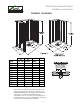
6. Carefully measure the framing pocket to assure it is of
proper size for the unit to be installed. Refer to dimensional
information in the Framing Diagrams in Figure 1.
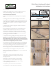
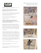
7. Check the framing pocket for square. Check to assure
the vertical studs are plumb. To have tight seams where
the parts meet, it is very important that the framing pocket
be exceptionally square and plumb.
Check for square by holding a measuring tape from the
back left corner to the front right corner, as shown in
Figure 4. Repeat for the other side. If both dimensions are
the same, the framing is square. Adjust if necessary.
8. The next step is to dry t the shower pan to the studs
and conrm the drain location.
The better t of the pan, the better all wall parts will
assemble as intended with minimal gaps at the seams.
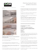
Note in Figure 5 the two installers have placed the shower
pan on the oor, and are pushing it into the installed position. One of
the installers is using a short piece of 2 x 4 wood to hold the front
of the shower pan off the oor. This will assist in moving the pan into
the installed position while preventing chipping the front edge if it
were to slide along the sub oor.
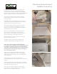
After the pan is set, ll any gaps between the mounting
ange and the framing with wood shims or furring strips to
achieve solid contact. The ange must be in contact with the
studs along all sides.
The back corners of the shower pan should be in
contact with the framing, as seen in Figure 7. Shim these areas if
required.
9. Once the shower pan is put into place and t is conrmed,
draw a pencil line on the sub oor indicating the front point of
the threshold of the pan. See Figure 8
Place a piece of cardboard in the oor of the shower to
protect the oor during the additional steps of installation.
There is a cut out for this on the pan box.
9.
Once the shower pan is put into place and
fit is confirmed, draw a pencil line on the sub floor
indicating the front point of the threshold of the pan.
(See Figure 8).
The back corners of the shower pan should be in
contact with the framing, as seen in Figure 7.
Shim these areas if required.
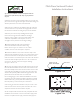
NOTE: There are 2 shower models that require shims
on the underside for installation. These models are:
When the shower pan is trial fit in the framing
pocket, shim under the leveling leg on the under
side of the pan. Place the shims and adjust
until the pan is level and does not rock.
These shims must be glued or screwed down in the
correct location before the final installation.
This step is required for these units to assure a correct
installation for these two higher threshold showers.
Place a piece of cardboard in the floor of the shower to
protect the floor during the additional steps of installation.
There is a cut out for this on the pan box.
5
After the pan is set, fill any gaps between the mounting
flange and the framing with wood shims or furring strips to
achieve solid contact. The flange must be in contact with
the studs along all sides.
Figure 7
Figure 8
Figure 5
Figure 6
8.
The next step is to dry fit the shower pan to the studs
and confirm the drain location.
The better fit of the pan, the better all wall parts will
assemble as intended with minimal gaps at the seams.
Note in Figure 5 the two installers have placed the shower
pan on the floor, and are pushing it into the installed
position. One of the installers is using a short piece of 2 x
4 wood to hold the front of the shower pan off the floor.
This will assist in moving the pan into the installed position
while preventing chipping the front edge if it were to slide
along the sub floor.
4836 SH 3.0, and 6030 SH 4.0.