Owner’s Manual LAVA LITE KD DANGER If you smell gas: 1. Shut off gas to the appliance. 2. Extinguish any open flame. 3. If odor continues, keep away from the appliance and immediately call your gas supplier or fire department. WARNING WARNING indicates an imminently hazardous situation which, if not avoided, will result in death or serious injury. WARNING Do not store or use gasoline or other flammable vapors and liquids in the vicinity of this or any other appliance.
PACKAGE CONTENTS A Reflector B Mesh P Mesh Base C Top Plate D Upper Support (Long) E Protective Guard F Glass Tube G Middle Cover H Control Box Assembly I Side Panel J Lower Support (Short) K Block Belt L Wheel Assembly M Bottom plate PART A B C D E F G H I J K L M DESCRIPTION Reflector Mesh Top Plate Upper Support (Long) Protective Guard Glass Tube Middle Cover Control Box Assembly Side Panel Lower Support (Short) Block Belt Wheel Assembly Bottom Plate QUANTITY 1 1 1 3 3 1 1 1
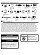
HARDWARE CONTENTS (shown actual size) AA BB Wing nut Qty. 3 GG CC Stud Qty. 6 Small flat washer Φ8 Qty. 6 HH Fixing Bracket Qty. 3 DD II Nut M8 Qty. 3 MM NN Chain Qty.1 SAFETY INFORMATION Screw M5 X 12 Qty. 42 JJ Cap nut M8 Qty. 3 EE KK Knob Qty. 1 OO LL Nut M4 Qty. 1 wafer Qty.1 PP Wrench Qty. 1 Screw M4 X 10 Qty.1 Bolt M6 X 10 Qty. 8 Philips screwdriver Qty. 1 This manual contains important information about the assembly, operation and maintenance of this patio heater.
SAFETY INFORMATION DANGER DANGER • EXPLOSION - FIRE HAZARD • Keep solid combustibles, such as building materials, paper or cardboard, a safe distance away from the heater as recommended by the instructions. • Provide adequate clearances around air openings into the combustion chamber. • Never use the heater in spaces which do or may contain volatile or airborne combustibles, or products such as gasoline, solvents, paint thinner, dust particles or unknown chemicals.
SAFETY INFORMATION WARNING WARNING California Proposition 65 Combustion by-products produced when using this product contain chemicals known to the State of California to cause cancer, birth defects, and other reproductive harm. • This product is fueled by propane gas. Propane gas is invisible, odorless, and flammable. An odorant is normally added to help detect leaks and can be described as a “rotten egg” smell. The odorant can fade over time so leaking gas is not always detectable by smell alone.
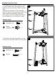
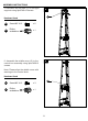
ASSEMBLY INSTRUCTIONS 1. Assemble the three lower supports (short) (J) to the bottom plate (M) and control box assembly (H) using the 9pcs M5X12 screws. Note : 2 people are required to do the assembly. Align the side of bottom plate with holes to the side of control box assembly with knob. Do not place the bottom plate upside down. Do not fasten the 3 pcs of M5X12 screws. 1 H DD Hardware Used J DD Screw M5 X 12 x9 PP Philips screwdriver x1 M 2 2.
ASSEMBLY INSTRUCTIONS 3. Secure the block belt (K) to the lower supports with 4pcs M5x12 screws (DD). 3 Hardware Used DD Screw M5 X 12 x4 PP Philips screwdriver x1 K 4 4. Connect three upper supports (long) (D) to the lower supports (short), secure them with 6pcs M5x12 screws (DD) and fasten the 3pcs M5X12 screws on control box assembly.
ASSEMBLY INSTRUCTIONS 5. Assemble the top plate (C) to the upper supports using 6pcs M5x12 screws. 5 C Hardware Used DD Screw M5 X 12 x6 PP Philips screwdriver x1 6 6. Assemble the middle cover (G) to the control box assembly using 3pcs M5X12 screws. Note: Please align the middle cover with warnings to the control knob.
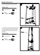
ASSEMBLY INSTRUCTIONS 7. Install the glass tube (F). Carefully install the glass tube between central of top plate and control box assembly. Make sure to place the lower end of the glass tube between the three clips on the control box assembly. 7 F Make sure the end of glass tube is inserted in three clips of control box assembly. 8. Lean the heater carefully. Install 3pcs studs (CC) on the top plate,secure them with 3pcs M8 cap nuts (II).
ASSEMBLY INSTRUCTIONS ASSEMBLY INSTRUCTIONS 9. Install 2pcs side panels (I) with 8pcs M5x12 screws. Note : Do not cover the front panel where the control knob is located. 9 Hardware Used DD PP Screw M5 X 12 Philips screwdriver x8 x1 I 10. Assemble the chain (MM) and wafer (LL) to the inside of front panel (N) with M4x10 screw (NN) and M4 nut (KK) and then install the knob (JJ) to M4x10 screw.
ASSEMBLY INSTRUCTIONS 13. Connect one end of gas hose to the control box assembly and regulator. Connect one end of gas hose onto the thread of control box assembly. Tighten both connexions. Do not cross-thread. Connect the other end of gas hose to the regulator. Tighten them. Do not cross-thread. WARNING! Ensure gas hose does not contact any high temperature surfaces, or it may melt and leak causing a fire. 13 14. Connect regulator to cylinder.
ASSEMBLY INSTRUCTIONS Warning: A dented, rusted or damaged propane cylinder may be hazardous and should be checked by your propane supplier. Never use a propane cylinder with a damaged valve connection. The propane cylinder must be constructed and marked in accordance with the specifications for LP gas cylinders of the U.S. Department of Transportation (DOT) or the standard for cylinders, spheres and tubes for transportation of dangerous goods and commission, CAN/CSA-B339.
OPERATION INSTRUCTIONS Leak Check WARNING • Perform all leak tests outdoors. • Extinguish all open flames. • NEVER smoke while carrying out the leak test. • Do not use the heater until all connections have been leak tested and do not leak. Hose / Regulator connection Regulator / Cylinder connection 1. Make 2-3 oz. of leak check solution (one part liquid dish washing detergent and three parts water). 2. Apply several drops of solution where hose attaches to regulator. 3.
OPERATION INSTRUCTIONS DANGER • CARBON MONOXIDE HAZARD • For outdoor use only. Never use inside house, or other unventilated or enclosed areas. This heater consumes air (oxygen). Do not use in unventilated or enclosed areas to avoid endangering your life. Caution: Do not attempt to operate until you have read and understand all General Safety Information in this manual and all assembly is complete and leak checks have been performed. Before Turning Gas Supply ON: 1.
OPERATION INSTRUCTIONS 4. Push and release the igniter button until pilot flame is visible through the glass tube. 5. Once the pilot is lit, continue to depress the control knob for 30 seconds. 6. If the pilot does not stay lit, repeat steps 4 to 6. 7. If after repeating steps 4 to 6 unit does not light, then -Push in control knob and turn counterclockwise to “PILOT” (Figure 3). -As you are depressing the control knob, place long stem lighter through the glass tube to light the pilot (Figure 4).
OPERATION INSTRUCTIONS WARNING FOR YOUR SAFETY Be careful when attempting to manually ignite this heater. Holding in the control knob for more than 20 seconds before igniting the gas will cause a ball of flame upon ignition. When heater is ON: The flame should be blue with straight yellow tops. If excessive yellow flame is detected, turn off heater and consult “Troubleshooting” on page 19.
OPERATION INSTRUCTIONS 9. Heater is away from gasoline or other flammable liquids or vapours. 10. Heater is away from windows, air intake openings, sprinklers and other water sources. 11. Heater is located at least 24" (top) / 36" (sides) from combustible materials. 12. Heater is on a hard and level surface. 13. There are no signs of spider or insect nests. 14. All burner passages are clear. 15. All air circulation passages are clear. 16.
TROUBLESHOOTING PROBLEM POSSIBLE CAUSE CORRECTIVE ACTION Cylinder valve is closed Open valve Blockage in orifice or pilot tube Pilot won’t light Air in gas line Note: Heater operates Low gas pressure with cylinder valve fully open at reduced efficiency below 40ºF (5ºC) Igniter fails Pilot won’t stay lit Clean or replace orifice or pilot tube Open gas line and bleed it (pressing control knob in) for no more than 1 - 2 minutes or until you smell gas Turn cylinder valve OFF and replace cylinder Use
CARE AND MAINTENANCE Spiders and insects can nest in burner or orifices. This dangerous condition can damage heater and render it unsafe for use. Clean burner holes by using a heavy-duty pipe cleaner. Compressed air may help clear away smaller particles. Carbon deposits may create a fire hazard. Disassemble the reflector, unscrew the reflector spacer, take off the screen, take down one side of protective guards. Then take the glass tube from the heater and wash and clear.
FIVE-YEAR LIMITED WARRANTY The appliance has been manufactured under the highest standards of quality and workmanship. We warrant to the original consumer purchaser that all aspects of this product will be free of defects in material and workmanship for five (5) year from the date of purchase. A replacement for any defective part will be supplied free of charge for installation by the consumer. Defects or damage caused by the use of other than genuine parts are not covered by this warranty.