Owner’s Manual OPUS LITE DANGER If you smell gas: 1. Shut off gas to the appliance. 2. Extinguish any open flame. 3. If odor continues, keep away from the appliance and immediately call you gas supplier or fire department. WARNING WARNING indicates an imminently hazardous situation which, if not avoided, will result in death or serious injury. WARNING Do not store or use gasoline or other flammable vapors and liquids in the vicinity of this or any other appliance.
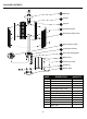
Pilot PACKAGE CONTENTS Hi Igniter Lo PART A B C D E F G H I J K L 2 A Reflector B Emitter C Support D Protective Guard E Borosilicate Glass Tube F Burner Ignition Plate G Control Box Casing H Gas Hose & Regulator I Back Panel J Front Door Panel K Wheel Kit L Bottom plate DESCRIPTION Reflector Emitter Support Protective Guard Borosilicate Glass Tube Burner Ignition Plate Control Box Casing Gas Hose & Regulator Back Panel Front Door Panel Wheel Kit Base plate QUANTITY 1 1 3 3 1
INCLUDED HARDWARE OO EE HH DD Wrench Qty. 1 Bolt Ø10 ×15mm Qty. 2 Nut M8 Qty. 2 Screw Ø8×15 mm Qty. 10 ADDITIONAL REQUIRED HARDWARE SAFETY INFORMATION Please read and understand this entire manual before attempting to assemble, operate or install the product. This manual contains important information about the assembly, operation and maintenance of this patio heater. General safety information is presented in these first few pages and is also located throughout the manual.
SAFETY INFORMATION DANGER DANGER DANGER WARN DANGER 4
SAFETY INFORMATION WARNING WARNING California Proposition 65 Combustion by-products produced when using this product contain chemicals known to the State of California to cause cancer, birth defects, and other reproductive harm. is invisible, odorless, and flammable. An odorant is normally added to help detect leaks and can be described as a “rotten egg” smell. The odorant can fade over time so leaking gas is not always detectable by smell alone. WARNING will sink to the lowest level possible.
ASSEMBLY INSTRUCTIONS 1. Heater is partially preassembled at the factory. User needs to complete a couple of assembly procedures to make the appliance operational. First, please ensure all transit protection (foam, cardboard, buuble wrap, etc.) is removed. Next identify the 4 main items listed and illustrated to the right. 1 Top portion Bottom panels Wheel kit Base plate 2.
ASSEMBLY INSTRUCTIONS 3. Align bottom panel on top of base plate and connect them together by securely installing (5) M5 X 12 screws through the designated 90 degree metal brackets with a philips screwdriver. 3 Hardware Used DD Screw Ø8×15 mm x5 PP Philips screwdriver x1 4. Align top portion on top of bottom panel and connect them together by securely installing (5) M5 X 12 screws through the designated 90 degree metal brackets with a philips screwdriver.
ASSEMBLY INSTRUCTIONS 5.You will need to remove at least one of the three protective steel guards (D) in order to safely remove the bubble rap and foam material from the boroscilate glass tube located in the center of the unit. Unscrew all (4) of the MM Ø8×10 mms screws, then remove the protective steel guard from its supports slots. Now that you have properly and carefully removed all transit protection materials from the unit, you will need to place the unit back in its original proper order.
ASSEMBLY INSTRUCTIONS 7. Connect hose and regulator to cylinder. The propane gas and cylinder are sold separately. Use a standard 20 lb. propane cylinder only. Use this heater only with a propane vapor withdrawal supply system. See chapter 12 of the standard for storage and handling of liquefied petroleum gas, ANSI/NFPA 58 or CSA B149.1, Natural Gas and Propane Installation Code. Your local library or fire department should have this book.
OPERATION INSTRUCTIONS DANGER Caution: Do not attempt to operate until you have read and understand all General Safety Information in this manual and all assembly is complete and leak checks have been performed. Note: This heater is equipped with a pilot light that allows for safer startups and shutdowns. Pilot must be lit before main burner can be started. Figure 1) Note: For initial start or after any cylinder change, hold control knob in for 2 minutes to purge air from gas lines before proceeding.
OPERATION INSTRUCTIONS 4. Push and release the igniter button until pilot flame is visible through the glass tube. 5. Once the pilot is lit, continue to depress the control knob for 30 seconds. 6. If the pilot does not stay lit, repeat steps 4 to 6. 7. If after repeating steps 4 to 6 unit does not light, then -Push in control knob and turn counterclockwise to “PILOT” (Figure 3). -As you are depressing the control knob, place long stem lighter through the glass tube to light the pilot (Figure 4).
OPERATION INSTRUCTIONS WARNING FOR YOUR SAFETY Be careful when attempting to manually ignite this heater. Holding in the control knob for more than 20 seconds before igniting the gas will cause a ball of flame upon ignition. When heater is ON: The flame should be blue with straight yellow tops. If excessive yellow flame is detected, turn off heater and consult “Troubleshooting” on page 18.
OPERATION INSTRUCTIONS 9. Heater is away from gasoline or other flammable liquids or vapors. 10. Heater is away from windows, air intake openings, sprinklers and other water sources. 11. Heater is at least 24 in. on top and at least 36 in. on sides from combustible materials. 12. Heater is on a hard and level surface. 13. There are no signs of spider or insect nests. 14. All burner passages are clear. 15. All air circulation passages are clear. 16.
CARE AND MAINTENANCE Gas odor with extreme yellow tipping of flame. Heater does NOT reach the desired temperature. Heater glow is excessively uneven. Heater makes popping noises. Spiders and insects can nest in burner or orifices. This dangerous condition can damage heater and render it unsafe for use. Clean burner holes by using a heavy-duty pipe cleaner. Compressed air may help clear away smaller particles. Carbon deposits may create a fire hazard.
TROUBLESHOOTING PROBLEM POSSIBLE CAUSE CORRECTIVE ACTION Cylinder valve is closed Open valve Blockage in orifice or pilot tube Pilot won’t light Air in gas line Note: Heater operates Low gas pressure with cylinder valve fully open at reduced efficiency below 40ºF (5ºC) Igniter fails Clean or replace orifice or pilot tube Open gas line and bleed it (pressing control knob in) for not more than 1 - 2 minutes or until you smell gas Turn cylinder valve OFF and replace cylinder Use match to light pilot;