
Use and Care Manual


User Manual of LV-D2104CS,LV-D2108CS,LV-D2116CS Series DVR
15
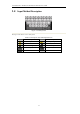
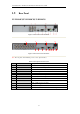
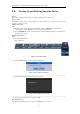
1.5 Rear Panel
LV-D2104CS,LV-D2108CS,LV-D2116CS:
Figure 1.4 Rear Panel of LV-D2104CS
1 2
3 4 5
6
7 8 9 10
11
12
Figure 1.5 Rear Panel of LV-D2116CS
Note: The rear panel of LV-D2108CS provides 8 video input interfaces.
Table 1.5 Description of Rear Panel
No.
Item
Description
1
VIDEO IN
BNC connector for analog video input.
2
VIDEO OUT
BNC connector for video output.
3
USB Interface
Connects USB mouse or USB flash memory devices.
4
HDMI
HDMI video output.
5
VGA
DB15 connector for VGA output. Display local video output and menu.
6
AUDIO IN
RCA connector for audio input.
7
AUDIO OUT
RCA connector for audio output.
8
LAN Interface
RJ45 10M/100M Ethernet interface.
9
RS-485 Interface
Connector for RS-485 devices. Connect the D+ and D- terminals to T+
and T- of PTZ receiver respectively.
10
12V
12VDC power supply.
11
POWER
Switch for turning on/off the device.
12
GND
Ground (needs to be connected when DVR starts up).