
User's Manual


5
10
9
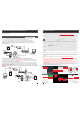
1.4 Wiring Diagram
DOOR1
DOOR2
Power
ISP
DC12V
GND
AUDIO
VIDEO
GND
DC12V
AUDIO
VIDEO
GND
DC12V
NET
DOOR1
DOOR2
AUDIO
VIDEO
GND
DC12V
AC/DC power
lock
AUDIO
VIDEO
GND
DC12V
AC/DC power
lock
DOOR2
DOOR1
internet
ISP
(not Included)
(not Included)
(not Included)
(not Included)
A: For the visual indoor unit with 7 inch or 4 inch TFT LCD monitor, users can connect up to
two outdoor cameras to the corresponding interfaces by their own’s requirement according
to the following wiring diagram. And indoor device power with a built-in power or an external
power optional, please refer to actual control using.
B: For the non-visual indoor unit, users can connect only one outdoor camera to the
corresponding interface according to the following wiring diagram. And indoor machine
power with a built-in power or an external power optional, please refer to actual control
using.
AUDIO
VIDEO
GND
DC12V
DOOR1
AUDIO
VIDEO
GND
DC12V
DOOR
AC/DC power
lock
(not Included)
(not Included)
internet
External switching power supply(optional)
DC 12V
DOOR1
V
GND
A
DC
B. For the non-visual indoor unit
Indoor Unit -------------------------------------------------------------------------------------- 1 pcs
4 Pin Line --------------------------------------------------------------------------------------- 1 pcs
This Quick Guide------------------------------------------------------------------------------ 1 pcs
External Switching Power Adapter--------------------------------------------------------- 1 pcs
Installation CD(with full manual and android mobile phone software)-------------- 1 pcs
Plastic Anchors ------------------------------------------------------------------------------- 2 pcs
Screws ------------------------------------------------------------------------------------------ 2 pcs
1.5 Note On Wiring Connection
The electric lock source camera is not include in the package, you can purchase an electric lock which is suitable
for you need.
In the standard delivery the system supports locks with Normally Open (N.O.) door unlocking method. It means that
in the normal state the dry contact is opened so the lock is kept under constant closed state. If the unlocking
push-button is pressed and the dry contact is changed to closed, then the lock is released.
Indoor machine power with a built-in power and the external power optional. Please refer
to actual control using. If the indoor machine with a built-in power source, applicable to
wide voltage range(AC 100V~240V). Please first pull out the AC power plug before
installation of device(Shown as below).
Please note that the 2P Short Pin is designed for programming the indoor monitor, the indoor monitor will
be programmed to main monitor if you plug the 2P Short Pin in; however the indoor monitor will be
programmed to extension monitor if the 2P Short Pin is pulled out. Setup ok, after power machine
automatically detects, if it is in state machine work Set, need makes the machine to detect electric.
Use and selection of wire, please refer to the following.(The actual effect and the quality of wire
rod has the very big relations)
1. 4C ordinary unshielded and shielded wire connection mode:
Distance
≤28m(4*0.2mm);
2
Distance
≤50m(4*0.3mm
2
)
;
Distance
≤80m(4*0.5mm ).
2
Talk
Unlock
Hang up
OPERATION INS
IP Villa Video Intercom Sys
Quick Guide