
Installation Guide
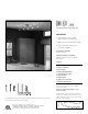
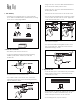
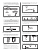

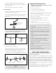

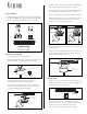
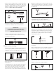
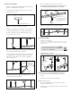
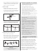
Table Of Contents

1. Take Inventory
– Unpack the box containing (3) pieces of rail, (5) Heads,
(
5) 20 watt 12 volt MR16 bulbs (1) transformer, (3) ceiling
posts, (1) box of mounting hardware
(1) TRANSFORMER
(5) HEADS
(3) PIECES OF RAIL
(3) CEILING POSTS
(
- TRANSFORMER HARDWARE
- RAIL JOINERS
- CEILING POST HARDWARE
-
SPARE PARTS
(5) MR16 BULBS
R
ail
K
it
2. Install The Transformer
– Turn off the power to the electrical box.
– Locate the transformer and the transformer mounting
hardware packet, which contains (2) screws and
(3) wire nuts.
TRANSFORMERTRANSFORMER
– Remove and set aside the three screws from the side of
the transformer to release the back plate.
– In accordance with local electrical codes, connect the
transformer ground wire to the electrical box ground wire
(typical installation shown).
– Using a wire nut, connect the white transformer wire to
the electrical box neutral power line wire.
– Using a wire nut, connect the black transformer wire to
the hot power line wire.
– Place the wire nut connections into the electrical box.
– Line up the back plate with the two screw holes located
on the electrical box and insert the screws. Tighten the
screws until the back plate is secure.
– Tuck the wires into the housing and slide the housing
back onto the backplate.
– Line up the transformer housing with the three screw
holes on the back plate. Tighten the screws until the
transformer housing is secure.
3. Prepare The Rail
– Locate the three pieces of rail and the rail joiner packet,
which contains (2) rail joiners, (1) Allen wrench and
several extra set screws.
– If you would like to shorten the length of the rail system,
the rail can be cut with a hacksaw. End caps can be
removed and placed over the cut end of the rail.
– If not bending the rail, skip the next step.