
Users Manual


150-160cm
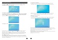
1. Description Of The Indoor Monitor
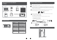
1.1 Fittings
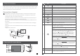
1.2 Specifications
5
6
For indoor monitor
LAN
OPERATION INS
IP Villa Video Intercom Sys
Quick Guide
Indoor monitor
(1pcs)
Screw anchors
(4pcs)
Wall screws
(4pcs)
Bracket
(1pcs)
A Network Conversion
Line with 4 pin interface
(1pcs)
User Manual
(1pcs)
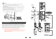
1.3 Note On Wiring Connection
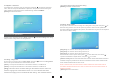
1.4 Installation Process
4 Pin line
(5pcs)
In the standard delivery the system supports locks with Normally Open (N.O.) door unlocking
method. It means that in the normal state the dry contact is opened so the lock is kept under
constant closed state. If the unlocking push-button is pressed and the dry contact is changed
to closed, then the lock is released.
The electric lock/source/camera is not include in the package, you can purchase an electric
lock which is suitable for your need.
Wiring connection according to the following to avoid interference:
Power+ Video
Audio
GND
GND
Audio
Power+ Video
Please note the silk printing marked on PCB in order to avoid incorrect connecting.
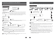
The wiring connection :requirement
1. 4C ordinary non-STP wiring cable;
2. Effective distance from the outdoor camera to furthest indoor monitor:
2
Transmission ≤28m (4x0.2mm )
2
Transmission ≤50m (4x0.3mm )
2
Transmission ≤80m (4x0.5mm )
Display screen
Definition
Standard
Calling mode
Calling time
Standby current
Work current
Power supply
Work temperature
Installation way
7"TFT LCD screen
PAL/NTSC
Two-way conversation
120s
Maximum 400MA
Maximum 800MA
Surface mounting
TF card
(maximum 64GB)(>CIass 10)
Extension memory
1024(H)X600(V)
-10 C~+60 C
DC 12V
Monitoring
Unlock
Talk
Hang up
1
2
Monitoring
Unlock
Talk
Hang up
1
2
236mm
TF
142mm
14mm
External Switching
Power Adapter--DC
12V(1pcs)--Optional
Please check that the socket of power supply(silk printing J8) is correct if you connect
the external switching power supply, otherwise it will damage the device.