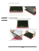
D I S A S S E M B L Y 3 P R O C E D U R E Chapter Disassembly Procedure Please follow the information provided in this section to perform the complete disassembly procedure of the notebook. Be sure to use proper tools described before. A SUS M6000 Series Notebook consists of various modules. This chapter describes the procedures for the complete notebook disassembly. In addition, in between procedures, the detailed disassembly procedure of individual modules will be provided for your service needs.
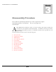
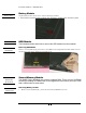
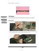
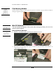
D I S A S S E M B L Y B A T T E R Y H D D H D D M O D U L E M O D U L E R E M O V A L P R O C E D U R E Battery Module The illustration below shows how to remove the battery module. 1. Press latch to open the battery module, then lift battery module away from the system. HDD Module The illustrations below show how to remove the HDD module from the notebook.
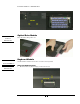
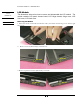
D I S A S S E M B L Y P R O C E D U R E M2*3L O P T I C A L D R I V E Optical Drive Module Press latch here then pull it out. R E M O V A L K E Y B O A R D Keyboard Module The illustration of below shows how to remove the keyboard D I S A S S E M B L Y K / B C O V E R R E M O V A L Removing Keyboard Cover 1. Remove 2 screws (M2.5*6L(K)) on the bottom case. M2.
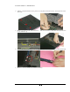
D I S A S S E M B L Y P R O C E D U R E 2. Unlock 3 keyboard latches then pull out the keyboard forward and lay the keyboard on the front side . 3. Remove 2 screws on the keyboard cover , then use tweezers to disconnect the keyboard two covers and lift it up. M2*3L 4. Loosen the switch board cable and take the keyboard cover away , then remove the switch cable 5. Remove 7 screws and take the switch board away.
D I S A S S E M B L Y P R O C E D U R E M2*3L C P U M O D U L E R E M O V A L C P U R E M O V A L CPU Module The illustrations below show how to remove the CPU module from the notebook. Removing CPU 1. Take the Fan bracket away then remove 4 screws (M2*6L(K)). M2*6L 2. Remove Thermal module and open the CPU Socket’s latch to loosen the CPU.(The use the CPU vacuum hand pump to “suck up” the CPU and lift the CPU away.
D I S A S S E M B L Y F I R S T M E M O R Y M O D U L E P R O C E D U R E First Memory Module The first memory module is under keyboard. Open the two latches to pop up memory module at 45 degrees angle then pull it out . R E M O V A L W I R E L E S S L A N M O D U L E W I R E L E S S L A N Mini PCI Module This slot usually has Wireless LAN module when leaving the factory, this slot is for optional system upgrade. Removing Wireless LAN Module 1.
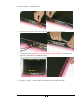
D I S A S S E M B L Y L C D M O D U L E L C D R E M O V A L P R O C E D U R E LCD Module The illustrations below show how to remove and disassemble the LCD module. The module contains LCD panel, Inverter board, LCD Hinge bracket, Hinge cover, LCD front cover, LCD back cover Removing LCD Module 1. Disconnect LCD coaxial cable and Inverter cable , then detach the left hinge cover and the right hinge cover. 2. Remove 2 screws (M2.5*6L(K)) at bottom case. M2.5*6L M2.5*6LL 3.
D I S A S S E M B L Y P R O C E D U R E 4. Remove 2 screws(M2.5*6L(K)) at top side, then lift the LCD module away from the system. M2.5*6L L C D D I S A S S E M B L Y Disassembling LCD Module 1. Remove 4 rubber pads and 4 screws(M2.5*6L(K)) from LCD module. M2.5*6L 2. Prying the inside edges of the top front bezel, then separate it from LCD back cover and take LCD front bezel away. 3. Remove 1tape and the other tape here.
D I S A S S E M B L Y P R O C E D U R E 4. Disconnect the speaker cable and LCD cable then take Inverter board off. 5. Remove 8 screws (M2*3L(K) x 4 ,(M2*6L(K) x2 ,(M2.5*4L(K) x 2) and 2 fixed slices off , then take the LCD Bracket away. M2.5*4L 6. Remove 7 tapes、2 screws and 2 screws(M2*3L(K)) on the other side.
D I S A S S E M B L Y P R O C E D U R E M2*3L T O P C A S E 7. Detach the right & left antenna and its cable. 8. Reomve the speaker cable, then remove 1screw(M2*3L(K)) and 1 screw on the other side.Then take two speaker s away M O D U L E M2*3L speaker 9. Detach the LCD hooker and spring then take it away.
D I S A S S E M B L Y P R O C E D U R E 10. Remove 1 screw (M2.5*4L(K)) and 1 screw on the other side, then take right and lift hinge off. M2.5*4L M2.5*4L 11. Remove 2 tapes and dissconnect coaxial cable then take it away. 12. Finally, Remove 4 screws(M2*3L(K)) on the right LCD bracket , and 4 screws on the ilft side to disassemble LCD brackets.
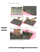
D I S A S S E M B L Y P R O C E D U R E M2*3L M2*3L Top Case Module The illustrations below show how to disassemble and remove the top case module of the notebook. T O P C A S E M O D U L E Removing Top Case Module 1. Remove 5 screw pads and 5 screws(M2*3L*(K)) on top side. R E M O V E M2*3L 2. Remove 7 screws (M2*6L(K)) on top case and 16 screws (M2*3L(K)+M2*6L(K)) on bottom case.
D I S A S S E M B L Y P R O C E D U R E M2*6L M2*3L M2*6L Removing touch pad 3. Loosen the touch pad FPC cable then separate the top case module from the bottom case module. 4. Disconnect touch pad FPC cable and remove 5 screws(M2*3L(K)) then take touch pad backet off and take touch pad away. M2*3L M O T H E R B O A R D M O D U L E M D C M O D U L E R E M O V A L Motherboard module The illustrations below show how to disassemble and remove the Motherboard module Removing Motherboard Module 1.
D I S A S S E M B L Y P R O C E D U R E M2*6L 2. Take the VGA heat sink module away and remove 2 tapes then disconnect modem cable. M O T H E R B O A R D R E M O V A L 3. Loosen the audio FPC and FAN cable. 4. Remove 1 screw(M2*6L(K)) then take the optical drive FPC away.
D I S A S S E M B L Y P R O C E D U R E M2*6L 5. Take the optical drive FPC away and remove 6 screws(M2*6L(K)). M2*6L 6. Remove the audio FPC and pull out the card reader dummy & PCMCIA dummy. Finally, pull out the motherboard from the bottom case carefully.
D I S A S S E M B L Y B O T T O M C A S E M O D U L E P R O C E D U R E Bottom Case Module The illustrations below show how to disassemble and remove the bottom case module of the notebook. 1. Remove 2 screws(M2*3L(K)) then take the modem board away. M2*3L 2. Remove 1 screw tape then loosen the speaker cable. 3. Remove 1 screw (M2*3L(K)) then take the LED board away.
D I S A S S E M B L Y P R O C E D U R E M2*3L 4. Remove 1 screw (M2*6L(K)) then remove the MIC out the hole and pull out the audio board upward then take it away. M2*6L 5. Remove 1 tape then take the MIC away. 6.
D I S A S S E M B L Y P R O C E D U R E 7. Remove 1 screw (M2*6L(K)) and 1 screw on the other side and then take 2 speakers away. M2*6L M2*6L 8. Finally, Remove 2 screws (M2.5*4L(K)) then take the FAN module away. M2.