
User manual


5
DEUTSCHFRANCAIS
ESPAÑOL
ENGLISH
ITALIANO POLSKI
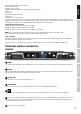
1
POWER
On / Off switch with LED display. The power LED lights up once the system is properly connected to the power mains and is switched on.
2
DISPLAY
Multi-functional OLED graphics display for displaying information such as active microphone, radio frequency and audio signal level. Also
indicates the menu items in order to adjust system settings as desired.
3
MIC RX1 - RX4
Illuminated switch to select the receiving channels 1 to 4.
4
PUSH TO ENTER
Combined pressure rotary encoder to access the Edit menu and to select and edit individual menu items.
5
Infrared interface for synchronising the relevant system settings of the transmitter with the receiver (e.g. transmission frequency).
6
Device for attaching the antennae for rack installation. Remove the covers, attach the BNC adapter to the front panel and connect the
BNC antenna connectors on the back to the BNC adapters on the front panel (short antenna cable and BNC adapter included). Now, the
antennae can be attached to the front of the receiver.
7
Screw holes for 19" rack mounting.
Overview of the frequency ranges
LDU505CS4 - Wireless Conference System 554 - 586 MHz
LDU506CS4 - Wireless Conference System 662 - 694 MHz
LDU508CS4 - Wireless Conference System 823 - 832 MHz + 863 - 865 MHz
NOTE: The use of wireless microphone systems may require a license (depending on the frequency rage and country).
For more detailed information, please contact the competent authority in your country.
Scope of delivery:
LDU50xCS4: Quad receiver plus 4 x microphone stations with gooseneck microphone, power supply, 2 x BNC antennae, 8 x AA batteries,
rack kit, Mini- DIN cable, data-link cable, instructions.
An extensive selection of suitable LD U500CS4 single components and accessories can be found at WWW.LD-SYSTEMS.COM
CONNECTIONS, CONTROLS AND INDICATORS
RECEIVER
7 6 3
2
5
4
1
6 7
Wireless True Diversity UHF conference system
Automatic channel search
Automatic frequency search
Infrared frequency synchronisation of the receiver and microphone unit
Pilot tone
Priority circuit
Automatic and manual gate modes
Security lock
RS-232 interface for external control
The pilot tone feature protects a wireless microphone system against interference from unwanted signals, for example from other radio
equipment. The transmitter adds a second inaudible signal, the pilot tone, to the signal to be transmitted. The receiver identifies this as the
matching pilot tone and frees the corresponding signal. Signals without pilot tone remain muted.