
User manual

Littfinski DatenTechnik (LDT)
Operating Instruction
4-fold decoder for single coil
turnouts
from the Digital-Professional-Series !
1-DEC-DC-F Part-No.: 110412
>> finished module <<
Compatible to the DCC-Format:
Turnouts can also be controlled via loc-addresses
(e.g. Lokmaus 2® and R3®).
For the digital control of:
⇒ up to four LGB turnout drives.
(LGB Part No. EPL 12010)
⇒ up to four PIKO G turnout drives.
(PIKO Part No. 35271)
⇒ up to four KATO UNITRACK, TOMIX and
ROKUHAN turnout drives.
⇒ switching current up to 1 Ampere on each
output.
This product is not a toy! Not suitable for children under 14 years of age! The kit
contains small parts, which should be kept away from children under 3! Improper
use will imply danger of injuring due to sharp edges and tips! Please store this
instruction carefully.
CE Part-No.:
71 32 47
yellow point
Introduction/Safety instruction:
You have purchased the 4-fold turnout decoder 1-DEC-DC for
your model railway a kit or as finished module supplied within
the assortment of Littfinski DatenTechnik (LDT).
We wish you having a good time using this product.
The 1-DEC-DC decoder (receiver device is marked with a
yellow dot) is suitable for the DCC-Format as used by the
systems of Lenz-Digital Plus, Arnold-, Märklin-Digital=,
Intellibox, TWIN-CENTER, Roco-Digital, EasyControl, ECoS,
KeyCom-DC, Digitrax, DiCoStation and Zimo.
The decoder 1-DEC-DC can control the turnouts either via
turnout-addresses or via loc-addresses. Therefore is it
possible to switch the turnouts for example by using the push
buttons F1 to F4 of the Lokmaus 2® or R3®.
The finished module comes with 24 month warranty.
• Please read the following instructions carefully. Warranty will
expire due to damages caused by disregarding the operating
instructions. LDT will also not be liable for any consequential
damages caused by improper use or installation.
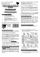
Connecting the decoder to your digital
model railway layout:
• Attention: Before starting any installation switch off all
power supply to the digital layout by pushing the stop
button or disconnect all main supply to the transformers.
The decoder receives the digital information via the clamp
KL2. Connect the clamp with a rail or even better connect the
clamp directly to the command station or to a booster
assuring the supply of digital information free from any
interference.
Pay attention to the mark at clamp KL2. The color markings
'Black/Schwarz' and 'Red/Rot' next to the clamp are used for
Arnold-Digital (old) and Märklin-Digital= .
The Lenz Digital plus systems uses the letters 'J' and 'K'.
If you use the decoder with Intellibox you have to connect the
digital wires to 'red/rot' and 'brown/braun'.
The correct connection for LGB is schwarz/K/rot (black/K/red)
= LGB BLUE and rot/J/braun (red/J/brown) = LGB RED.
The decoder receives the power supply via the two poles
clamp KL1. Voltage in the range of 12…18V~ is acceptable
(alternate current output of a model railway transformer) or
15...24 V= (direct voltage from a switched mode mains power
supply).
If you do not want to supply power to the decoder 1-DEC-DC
from an external transformer you can connect the clamp
KL1 to KL2 with two wires. In this case the decoder will get the
power supply complete from the digital system.
Connecting turnout drives:
The Decoder 1-DEC-DC is suitable for digital switching of
single coil turnout drives. Those drives contain two
connection wires. This wires shall be directly connected with
one of the output clamps KL6 to KL9.
ROKUHAN turnout drives shall be supplied with a voltage of
10 to 12 Volt only. For reducing the voltage is it required to
apply two 9,1Volt Z-Diodes on each output. The connection
sample 1275 to be downloaded from our internet site from the
section “Sample Connection” will show the wiring.
Programming the decoder address:
To program the decoder address a turnout drive has to be
connected to the output 1 (clamp KL9) of the decoder.
• Switch on the power supply of your model rail way.
• Press the programming key S1. Do not touch the
integrated circuits of the pc-board because any electrostatic
discharge can destroy the IC`s.
• The turnout drive connected to output 1 will now move every
1,5 seconds. This indicates that the decoder is in the
programming mode.
Switching turnouts via turnout addresses:
• Press now one key of a key group to be assigned to the
decoder. For programming the decoder address you can
also release a turnout switch signal via a personal computer
over the model railway software.