
Instructions

Littfinski DatenTechnik (LDT)
Operation Instruction
Light signal decoder
for light-signals with LED
from the Digital-Professional-Series !
LS-DEC-DB-F Part-No.: 512012
>> finished module <<
Suitable for the digital systems:
Märklin-Motorola and DCC
For digital control of:
⇒ up to four 2- or 3-aspect signals.
⇒ up to two 7-aspect signals (home- and advance signal on one
signal post).
⇒ for LED light signals with common anodes or common
cathodes.
Realistic operation of the signal aspects by implemented
dimming function and dark phase between the switching of
the signal aspects.
This product is not a toy! Not suitable for children under 14 years of age!
The kit contains small parts, which should be kept away from children under 3!
Improper use will imply danger of injuring due to sharp edges and tips! Please
store this instruction carefully.
CE Part-No.:
24 00 12
Label:
yellow point
or DB
Introduction/Safety instruction:
You have purchased the Light signal decoder LS-DEC-DB for your
model railway as a kit or as finished module.
The LS-DEC is a high quality product that is supplied within the Digital-
Professional-Series of Littfinski DatenTechnik (LDT).
We wish you having a good time using this product.
The light signal decoder LS-DEC of the Digital-Professional-Series
can be easily operated on your digital model railway.
By using a connector plug bridge you can choose if you want to
connect the decoder to a Märklin-Motorola system or to a digital
system with DCC standard.
The finished module comes with 24 month warranty.
• Please read the following instructions carefully. Warranty will expire
due to damages caused by disregarding the operating instructions.
LDT will also not be liable for any consequential damages caused by
improper use or installation.
Connecting the decoder to your digital model railway
layout:
• Attention: Before starting the installation-work switch off the
layout voltage supply (switch-off the transformers or disconnect
the main supply).
The Light signal decoder LS-DEC is suitable for the DCC data format
as used e.g. by Lenz-Digital Plus, Roco-Digital (switching via
Keyboard or multiMAUS only; switching via Lokmaus 2® and R3® is
not possible), Zimo, LGB-Digital, Intellibox, TWIN-CENTER,
DiCoStation, ECoS, EasyControl, KeyCom-DC and Arnold-Digital /
Märklin-Digital= whenever no connector plug bridge is inserted in
position J2.
The decoder is suitable for Märklin-Digital~ / Märklin Systems or
Märklin-Motorola (e.g. Control-Unit, Central Station, Intellibox,
DiCoStation ECoS, EasyControl, KeyCom-MM) if you insert a
connector plug bridge on J2.
The decoder receives the digital information via the clamp KL2.
Connect the clamp with a rail or even better connect the clamp to an
own digital main ring supply assuring the supply of digital information
free from any interference.
Please attend to the marking on clamp KL2. The colors 'red' and
'brown' next to the clamp are usually used by Märklin-Motorola
systems (e.g. Märklin-Digital~ / Märklin Systems / Intellibox /
DiCoStation / EasyControl).
Lenz-Digital systems are using the letters 'J' and 'K'.
In case you assemble the decoder to an Arnold-Digital (old)- or
Märklin-Digital= system, you have to connect 'black' to 'K' and 'red' to
'J'.
The decoder receives the power supply via the two poles clamp KL1.
The voltage shall be in a range of 14..18V~ (alternate voltage output of
a model rail road transformer).
If you do not want to supply voltage separately from a transformer to
the LS-DEC decoder you can shorten the clamp KL1 and KL2 with
two wires. In this case the decoder will get the power supply
completely from the digital network.
Connecting the signals:
General:
Up to 4 signals can be connected to the Light signal decoder LS-
DEC. Two signals per each 11poles clamp block. The build up of the
two clamps is identical. The following description refers mainly to one
clamp only. As you can see on the identical marking the description is
also valid for the second clamp.
Common connection:
All LED-signals of any manufacturer are designed in accordance to the
same principle. One wire of all light emitting diodes of a signal will be
generally connected to a common cable. Depending if all anodes or all
cathodes are connected together the signals will be called as common
anodes- respectively common cathodes-signal.
If you use signals with common anodes (e.g. supplied from Viessmann
or alphamodell) you have to clamp this cable to the connection marked
'+'. In addition you shall not insert the connection plug bridge in J1
in this case.
If you use signals with common cathodes you have to clamp this cable
to the connection marked '-'. In addition you shall insert the
connection plug bridge in J1 in this case.
The second connection of each light diode is separated and mostly
color marked at the end and contains a series resistor.
Series resistor:
Light diodes have always to be operated with a suitable series
resistor to prevent that they will be destroyed. For this prevention all
outputs have already a series resistor of 330 Ohm integrated on the
printed circuit board of the light signal decoder LS-DEC. Is there no
further external resistor the diode-current will be about 10mA.
This provides sufficient brightness.
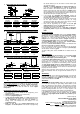
For assigning the single cables of the light diodes to the correct
clamp connection please attend to the below signal images. The
marks next to signal light diodes are not corresponding to the actual
light color but to the marking of the connection at the light signal
decoder LS-DEC.
If you do not know the correct allocation of the single wires to the light
emitting diodes you can test the function by connecting the wires to
clamp RT1 or RT2. These outputs are active because the decoder
switches all signals to red after switching on.