
Instructions


Littfinski DatenTechnik (LDT)
Assembly Instruction
Light signal decoder
for light-signals with LED
from the Digital-Professional-Series !
LS-DEC-DB-B Part-No.: 512011
(“yellow point” or label “DB”)
>> kit <<
Suitable for the digital systems: Märklin-Motorola and DCC
For digital control of:
⇒ up to four signals.
⇒ for LED light signals with common anodes or common
cathodes.
Realistic operation of the signal aspects by implemented
dimming function and dark phase between the switching of
the signal aspects.
This product is not a toy! Not suitable for children under 14 years of age!
The kit contains small parts, which should be kept away from children under 3!
Improper use will imply danger of injuring due to sharp edges and tips! Please
store this instruction carefully.
CE Part-No.:
24 00 11
Introduction:
You have purchased the light signal decoder kit LS-DEC for
your model railway supplied within the assortment of Littfinski
DatenTechnik (LDT).
• The LS-DEC kit is a high quality product which is easy to
assemble.
We are wishing you having a good time for assembling and
application of this product.
General:
Tools required for the assembly
Please assure that the following tools are available:
• a small side cutter
• a mini soldering iron with a small tip
• solder tin (if possible 0,5mm diameter)
Safety Instructions
• All electrical and electronic components included in this kit
shall be used on low voltage only by using a tested and
approved voltage transducer (transformer). All components
are sensitive to heat. During soldering the heat shall be
applied for a very short period only.
• The soldering iron develops a heat up to 400°C. Please keep
continual attention to this tool. Keep sufficient distance to
combustible material. Use a heat resistant pad for this work.
• This kit consist of small parts which can possibly be
swallowed from children. Children (especially under 3 years)
shall not participate on the assembly without supervision.
Set-Up:
For the board assembly please follow exact the sequence of the
below assembly list. Cross each line off as done after
completing the insertion and the soldering of the respective
part.
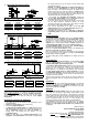
For the diodes please keep special attention to the correct
polarity (marked line for the cathode).
With reason to different makes of electrolytic capacitors you
will find different markings of the polarity. Some are marked with
"+" and some are marked with "-". Each capacitor has to be
assembled to the board that the marking on the capacitor is in
correspondence with the marking on the pc-board.
Resistor networks are marked for assembly with a printed
circle or a square at one end. Insert this component that way
that the marking corresponds with the marking between the first
and second bore on the pc board. Additionally has been the first
bore marked at the pc-board with a “1”.
Integrated circuits (IC`s) are either marked with a half round
notch on one end or a printed point for the correct mounting
position. Push the IC`s into the correct socket assuring that the
notch or the printed point is corresponding to the half-rounded
marking on the pc-board.
Please attend to the sensitivity of the IC`s to electrostatic
discharge which will cause immediate damage of the IC.
Before touching those components please discharge yourself
by contacting an earthed metal (for example an earthed
radiator) or work with an electrostatic safety pad.
Three 3-pole clamps and one 2-pole clamp each have to be
connected to 2 clamp-blocks of 11 poles each before assembly.
Assembly list:
Pos.
Qty.
Component
Remarks
Ref.
Done
1 1 Pc-board
2 2 Diode 1N4003 attend to the polarity! D1, D2
3 1 Diode 1N5819 attend to the polarity! D3
4 5 Networks 4*330Ohm attend to the polarity! R8..R12
5 2 Resistors 1,5kOhm brown-green-black-brown R1, R2
6 3 Resistors 18kOhm brown-gray-black-red R3, R4, R5
7 1 Resistor 220kOhm red-red-black-orange R6
8 1 Resistor 1MOhm brown-black-black-yellow R7
9 3 Capacitors 100nF 100nF = 104 C3, C4,C5
10 1 Pin plug bar J1, J2,J3
11 1 IC-socket 28poles IC1
12 2 IC-sockets 8poles IC2, IC4
13 1 IC-socket 6poles IC3
14 1 Resonator 16MHz CR1
15 2 Electrolytic cap. 220uF/35V attend to the polarity! C6, C7
16 1 Coil 330uH gold-brown-red-red L1
17 1 Push button S1
18 4 Clamps 2-poles KL1..KL4
19 6 Clamps 3-poles build blocks before assy´! KL5..KL10
20 1 IC: Z86E3016 attend to the polarity! IC1
21 1 IC: 24C01 attend to the polarity! IC2
22 1 IC: 4N25 or CNY17 attend to the polarity! IC3
23 1 IC: LM2574 attend to the polarity! IC4
24 final control
Made in Europe by
Littfinski DatenTechnik (LDT)
Kleiner Ring 9
D-25492 Heist/Germany
Phone: 0049 4122 / 977 381
Fax: 0049 4122 / 977 382
Internet: http://www.ldt-infocenter.com
Subject to technical changes and errors. 05/2013 by LDT
Märklin and Motorola are registered trade marks