Littfinski DatenTechnik (LDT) Kleiner Ring 9 • 25492 Heist/Germany • Phone: 0049 4122 / 977 381 • Fax: 0049 4122 / 977 382 Basic Manual Light-DEC The Light-DEC is a universal Layout-Light-Control for analogue and digital model railway layouts from the Digital-Professional-Series! Various light-functions can be assigned to up to 160 lightoutputs and can be automatically controlled within the daylight-cycle or can be switched ON or OFF via push buttons or DCC-Commands. Light-DEC-Basic-F Part-No.
Layout-Light-Control Light-DEC – Manual Content: Page 1. Introduction / Safety Instruction 2 2. Connect the Basic-Module to the first Light-Module 3 2.1. Using further Light-Modules 4 2.2. Connect light sources to the Light-Modules 5 3. Connect push-buttons or switches to the Basic-Module 7 4. Connect the Basic-Module with the digital layout 7 5. First starting-up / selecting language 8 5.1. Register external push-buttons or switches 9 5.2.
Layout-Light-Control Light-DEC – Manual 1. Introduction/Safety instruction You have purchased the Basic-Module for the Layout-Light Control Light-DEC for your model railway. The Basic-Module is a high quality product that is supplied within the assortment of Littfinski DatenTechnik (LDT). We are wishing you having a good time using this product. The finished module comes with 24 month warranty. • ·Please read the following instructions carefully.
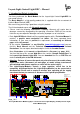
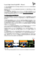
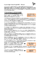
Layout-Light-Control Light-DEC – Manual 2. Connect the Basic-Module with the first Light-Module Connect the Basic-Module via the 10-poles socket bar BU1 either with a LightDisplay- or a Light-Power-Module. It is essential to attend careful to the position of the pin bar of the Light-Display- and the Light-Power-Module and that there is no offset to the socket bar of the Basic–Module.
Layout-Light-Control Light-DEC – Manual The first Light-Module has to be always directly connected onto the Basic-Module for voltage supply. Attend as well to the separate Operation Instruction of the Light-Display- or LightPower-Module. At the Operation Instruction you can find as well basic instruction for the connection of the power supply and the connection of model incandescent lamps or light emitting diodes (LED) within the section ”Connection of Illumination”. 2.1.
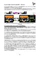
Layout-Light-Control Light-DEC – Manual It is as well possible to connect the Light-Modules to each other via the “Kabel Light@Night” at a distance of 0.5m, 1m or 2m. On this way can be as well older Light-Modules without RJ-45 sockets for a patchcable connection connected to each other on a longer distance of up to 2m.
K K+1 K+2 Layout-Light-Control Light-DEC – Manual K+2 K+1 K 16 15 14 24 23 22 21 20 19 18 17 Rev. 1.
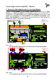
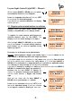
Layout-Light-Control Light-DEC – Manual 3. Connect push-buttons or switches to the Basic-Module The Basic-Module contains a 10-poles clamp bar for the connection of up to 8 PushButtons or Switches. Via those external push-buttons or switches is it possible to start or stop manually the Light-Control Light-Dec or single light-functions.
Layout-Light-Control Light-DEC – Manual Do not supply the digital voltage for the Basic-Module directly from the rails. DCC-Digital systems are using different cable colors or designations for both digital cables. Mostly used markings are printed next to clamp 5 but do not necessarily to be used because the Basic-Module will automatically evaluate the correct DCC-digital signal. 5.
Layout-Light-Control Light-DEC – Manual With the keys ABOVE or BELOW you can switchover between >Deutsch< and >English<. Language >Deutsch< Leave the language selection with the key LEFT for using now the selected language. If you would have selected >Deutsch< the display would show now: ---Hauptmenü---Sprache 5.1.
Layout-Light-Control Light-DEC – Manual Now select as well the set-up for the other-inputs or return with the key LEFT into the Main Menu: ---Main Menu---Buttons/Switches Activate again the key LEFT to store the selected adjustments at the Basic-Module. After a short delay the display of the Basic-Module will indicate the operation status: Light-DEC VX.X 22:30:00 A 300 5.2.
Layout-Light-Control Light-DEC – Manual 5.3. Light source test With the light source test can be the light sources of all single Light-Module outputs tested. Depress at first the key RIGHT longer than three seconds. The display changes into the Main Menu and all light sources will be switched off.
Layout-Light-Control Light-DEC – Manual Depress at the Main Menu the key BELOW several times shortly until the menu step start options will be indicated: ---Main Menu---Start options Open the menu start time with the key RIGHT.
Layout-Light-Control Light-DEC – Manual By calling the menu Start properties there will be always at first the property indicated which is presently active. Ex-factory this will be “Always active”. With the keys ABOVE or BELOW is it possible to select the Start property between >DCCAddress<, >Button/Switch< and >Always active<: Start property >Button/Switch< 6.1.1.
Layout-Light-Control Light-DEC – Manual Depress now the key LEFT several times until the Waiting for start-display will be shown after a warm start. The DCC-Address: 13 previous programmed DCC address will be indicated. If the basic-module receives the programmed DCC-address with the additional information of turnout straight the Light-Control will start with the adjusted starting time. If the programmed DCC-address with the additional information turnout round will be received the Light-control will stop.
Layout-Light-Control Light-DEC – Manual Select the day phases with the keys ABOVE or BELOW for your relevant adjustments. With the key RIGHT you will go to the adjustments of the selected day phases: Daybreak }06{ : 30 F: 300 With the keys LEFT and RIGHT you can select as usual the adjustments between }hour{, }minute{ and }factor{. Values between the curly brackets (} {) can be edited with the keys ABOVE or BELOW.
Layout-Light-Control Light-DEC – Manual Via the menu step Switching group can be the on- and off-switch times for the switch-groups individually adjusted. At first depress the key RIGHT longer than three seconds. The display will change into the Main Menu and all light sources will be switched off.
Layout-Light-Control Light-DEC – Manual After completing all adjustments at the switch groups you have to depress several times the key LEFT until after a warm start the operation mode will be displayed after a short time: Light-DEC VX.X 23:30:00 A 300 9. Available light functions The Light-DEC provides 44 light functions, which can be as well assigned several times to the outputs of the Light-Module.
Layout-Light-Control Light-DEC – Manual With the keys ABOVE or BELOW you can now select the light-function whose parameter shall be changed. Light options >Run light< For changing e.g. the speed of the light function Run light you have to activate the key RIGHT. Indicated will be the actual value: Speed } 200 { ms With the keys ABOVE and BELOW you can select now the value for the Run light speed suitable for your application.
Layout-Light-Control Light-DEC – Manual 11. Output function: assign light functions to the output of light modules Via the menu Output functions will be the outputs of the Light-Modules lightfunctions and their properties assigned, deleted or changed. Depress at first the key RIGHT longer than three seconds. The display will change into the Main Menu and all light sources will be switched off.
Layout-Light-Control Light-DEC – Manual Depress the key LEFT for deleting the preinstalled 1 = LDM-KL:01-08 initial functions. Now it will be indicated that the clamps 1 to 8 will be vacant. **** FREE **** With the key RIGHT you can change to the possibility to set-up a new light function as initial 1 = LDM-KL:01-02 function at this clamp section.
Layout-Light-Control Light-DEC – Manual 11.3. Output function: properties push button/switch If you want to activate or deactivate manually the output functions, which are connected via one of the 8 push buttons or switches to a Basic-Module you have to depress the key ABOVE or BELOW until the display indicates >Button/Switch<. Depress now the key RIGHT. If there was no external key determinates for the output function will be the display indicate “-“. Property Ext.
Layout-Light-Control Light-DEC – Manual 11.5. Output function: night function for traffic light pedestrian and traffic light cross road If one of the two light-functions traffic-light pedestrian or traffic-light cross-road has been set as output-function there can be “yellow” flashing individually activated for a night-function. At night the road light of the traffic light pedestrian or the road light of the side street will flash yellow.
Layout-Light-Control Light-DEC – Manual With the key ABOVE or BELOW you can select between Examples and Blank. Factory setting >Blank< >Examples< is for the possibility that output-functions will be preinstalled for the first Light-Display-Module (LDM). If you select >Blank< there will be no outputfunctions as factory-setting preinstalled. If you selected one of the two possibilities you can proceed with the key RIGHT to the security request.
Littfinski DatenTechnik (LDT) Kleiner Ring 9 • 25492 Heist/Germany • Phone: +49 (0)4122 / 977 381 • Fax: +49 (0)4122 / 977 382 K Technical Manual J red brown KL5 with Tables D1 and Light-DEC V1.0 12:15:00 T 300 IC5 graphic Menu Navigation for the universal layout-light-control BU1 S2 Light-DEC-Service Rev. 1.
Layout Light Control Light-DEC – Technical Manual Content: Page 1. Introduction 1 2. Graphical Menu-Navigation 2 3. Start-times and Time-factor at the Menus Start-adjustment and Day-phases 8 Switch groups with example: Working hours at the factory 9 4. 4.1. Switch group table for own adjustments 10 5. Description of the available light functions 6. Light options: Parameter of Light functions, which can be individually matched 13 Output functions: Factory settings 14 7. 7.1.
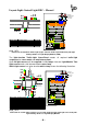
Layout Light Control Light-DEC – Technical Manual Identification of keys below the display of the basic-module. 2. Graphical Menu-Navigation By start via external button or switch. Button RIGHT Waiting for Ext. Button: x By start via DCCaddress. Waiting for DCC-Address: x By start via instant active. Light-DEC V1.0 22:30:00 A 300 For main menu, press the button RIGHT for more than three seconds.
Layout Light Control Light-DEC – Technical Manual Select: LPM for Light-Power-Module LDM for Light-Display-Module ---Main Menu---Light-Modules ---Main Menu---Lightsource test Module position No.: >x< = LxM Lightsource test Light-Module: >x< Module position No.: x = >LxM < Module: X = LxM Output : >x< Values between a larger and smaller sign can be edited step by step with the buttons UP and DOWN. The entry is set depending on the adjusted property.
Layout Light Control Light-DEC – Technical Manual Day phases >Daybreak< ---Main Menu---Day phases Daybreak Daybreak hh : }mm { F: xxx hh : mm F: }xxx { Day Day Day Day phases >Day< } hh { : mm F: xxx Day phases >Dusk< } hh{ : mm F: xxx hh : }mm { F: xxx hh : mm F: }xxx { Night Night Night Day phases >Night< ---Main Menu---Light options Daybreak } hh { : mm F: xxx hh : }mm { F: xxx Dusk Dusk } hh { : mm F: xxx hh : }mm { F: xxx Light options >Neon light< Switch time MIN: } x { ms
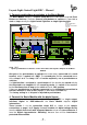
Layout Light Control Light-DEC – Technical Manual ---Main Menu---Light options Light options >Traffic l. ped< Pedestrian RED Light options >Traffic l. c< Pedestrian RED Light options >Traf. l. opt.
Layout Light Control Light-DEC – Technical Manual Module pos.:>x< LxM ---Main Menu---Output functions X=LxM-KL: XX-XX **** FREE **** X=LxM-KL:XX-XX > >Select Light function < X=LxM-KL: 01(-XX) Output function Output function Delete: >NO< Output function Delete: >YES< Entry-jump if selected module output functions have been already adjusted. Night function (YELLOW flashing) >ON< or >OFF< only by output function traffic light pedestrian and traffic light cross-road.
Layout Light Control Light-DEC – Technical Manual ---Main Menu---Switching group Switching group Switching group X No.
Layout Light Control Light-DEC – Technical Manual 3.
Layout Light Control Light-DEC – Technical Manual 4.
Layout Light Control Light-DEC – Technical Manual 4.1.
Layout Light Control Light-DEC – Technical Manual 5. Description of the available light functions Light function Railway cross Flash light Run light 4 Run light 5 Signal post Television Lamp Entrance hall House room House light Neon light Fireworks1 Fireworks2 Fireworks3 Ran. Fireworks Funfair1 to 8 Random Funfair Description Typical light flashing on railroad crossing with two synchronous contrary switching outputs. Generates ON- and OFF-times with simultaneous duration.
Layout Light Control Light-DEC – Technical Manual Light function Advert. sign1 to 8 Radio tower Chimney Welding light Camera flash Police light Fire Traffic light pedestrian Traffic light crossroad Car flash light Construction 5 Construction 8 ON / OFF Description 8 different effects for advertising signs, shops or for a fun-fair. The speed can vary. Creates flash effects as for radio- and TV-towers or other high buildings. With one time short flashing and following a longer pause.
Layout Light Control Light-DEC – Technical Manual 6.
Layout Light Control Light-DEC – Technical Manual 7. Output functions: Factory settings Module Position: 1 Module: Light-Display-Module (LDM) Name: Factory setting Clamp (s) 1-8 9 - 13 14 - 16 17 18 19 20 - 22 23 - 27 28 29 30 31 - 40 Output functions Characteristic Always active DCC-Address Random Funfair x Run light 5 x Television x Welding light x Radio tower x Fire x Signal post x Construction 5 x Police light x Police light x Car flash light.
Always active DCC-Address Button/Switch Switch group Clamp(s) Output functions Characteristic Name: Module: Module Position: Layout Light Control Light-DEC – Technical Manual 7.1.
For tantalum capacitors please attend to the connection wire marked "+". This wire has to correspond to the printed mark on the pc-board. The resistor-networks are marked at one end for the assembly position with “...103...” and additionally with a printed circle or a square. Assemble this component that way that the marking corresponds with the marking at the first bore of the pcboard. Additionally is the first bore marked with “1”.
Introduction: You have purchased the Basic-Module for the layout light control Light-DECBasis as a kit for your model railway supplied within the assortment of Littfinski DatenTechnik (LDT). These kits are of high quality and easy to assemble.
Littfinski DatenTechnik (LDT) Assembly Instruction Light-DEC-Service Module for Light-DEC from the Digital-Professional-Series ! >> kit << The Light-DEC-Service Module can only be used together with the Light-DEC-Basic Module. The unit has to be connected and screwed to the 20-poles socket bar of the basic module as described within the assembly instruction of the Light-DEC-Basic Module. Set-Up: For the board-assembly please follow exact the sequence of the below assembly list.
Soldering instruction Provided you have no special experience in soldering electronic components please read first this soldering instruction before starting the job. Soldering has to be trained! • Never use additional fluxes for soldering electronic circuits which contain acids (e.g. zinc chloride or ammonium chloride). Those can destroy components and printed circuits when not washed off completely. • As soldering material only lead free soldering tin with a rosin core for fluxing should be used.