
User manual

Layout-Light-Control Light-DEC – Manual
- 7 -
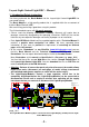
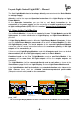
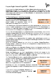
3. Connect push-buttons or switches to the Basic-Module
The Basic-Module contains a 10-poles clamp bar for the connection of up to 8 Push-
Buttons or Switches. Via those external push-buttons or switches is it possible to
start or stop manually the Light-Control Light-Dec or single light-functions.
BU1
GBS-Display / Light-Display
Rev. 1.8
braun
Littfinski DatenTechnik (LDT)
gelb
10...18V~
12...24V=
KL6
KL7
1
2
3
4
5
6
7
8
26
27
28
29
30
31
32
39
38
37
36
35
34
33
25
9
10
11
12
13
14
15
16
18
19
20
21
22
23
24
17
40
ST1
KL4 KL3 KL2 KL1
KL5
white
weiss
white
weiss
BU2
BU3
OUT
IN
BU1
Littfinski DatenTechnik (LDT)
Light-DEC-Basis
Rev. 1.0
Taster / Button
KL1 KL2 KL3 KL4
+5V
GND
1
2
3
4
5
6
7
8
IC5
D1
red brown
KL5
K J
Light-DEC-Service
Rev. 1.0
Littfinski DatenTechnik (LDT)
S1
S2
S4
S3
R1
Light-DEC V1.0
12:15:00 T 300
Leuchtdiode
light-emitting diode
Vorwiderstand
series resistor
Modellbahn-
lämpchen
model incandescent
lamp
braun
brown
gelb
yellow
Vom Modellbahntrafo
From transformer
Taster oder Schalter
Push button or switch
J
braun
brown
K
rot
red
Optional:
Von DCC-Digitalzentrale
oder Booster
From DCC command station
or booster
page_1612
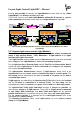
Up to 8 push-buttons or switches can be connected to the 10 poles clamp bar of the Basic-
Module.
One pole of the push buttons or switches has to be always connected to the earth
terminal, which is marked with “GND”. The second pole shall be connected to one
of the clamp 1 to 8. The clamp “+5V” will not be required by use of push-buttons or
switches.
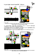
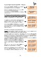
If a light-function is assigned to a push-button will the function be started with the
first keystroke and stopped with the second keystroke. If a switch will be used will
be the function active as long as the switch will be in “ON” position.
If there are push buttons or switches connected can be individually transmitted to
the basic module for each of the 8 inputs (as described at section 5.1).
The factory setting for all 8 inputs is adjusted to push buttons.
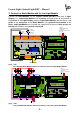
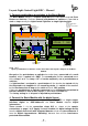
4. Connect the Basic-Module with the digital layout
If you want to start and stop the Light-Control Light-DEC or single output-
functions digital via DCC-addresses the Basic Module requires digital
informations.
Those receive it via the connection clamp KL5 as shown at the sample-
connections on page 1 to 5. Supply the basic module with digital voltage directly
from the digital central unit with integrated booster or from an external booster or
from the digital ring-conductor “Switching” because then will be interference-
protected data available.