
User manual


Layout-Light-Control Light-DEC – Manual
- 4 -
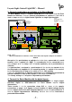
The first Light-Module has to be always directly connected onto the Basic-Module
for voltage supply.
Attend as well to the separate Operation Instruction of the Light-Display- or Light-
Power-Module.
At the Operation Instruction you can find as well basic instruction for the
connection of the power supply and the connection of model incandescent lamps
or light emitting diodes (LED) within the section ”Connection of Illumination”.
2.1. Using further Light-Modules
Via the Basic-Module is it possible to control with max. 7 Light-Modules up to 160
light-ouputs. A variable combination of Light-Display- and Light-Power-Modules is
possible.
A Light-Display-Module contains 40 and a Light-Power-Module 24 outputs. If there
are only Light-Power-Modules connected can be with 7 of those Modules (7 x 24 =
168 light-outputs) used. The last 8 outputs of the seventh Light-Power-Module
cannot be used for control connection because the maximum quantity of 160 light
outputs will be exceeded by 8.
If there are only Light-Display-Modules used with 40 outputs each there can be 4 of
those modules (4 x 40 = 160 light-outputs) used at the Basic-Module.
Combined used can be 5 to 7 Light-Modules used on one Basic-Module. If the
summary will be more than 160 light outputs will be the surplus outputs not
controlled.
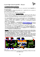
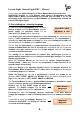
The Light-Modules shall be connected directly next to each other as shown at the
illustration on page 2 with one Light-Display- and one Light-Power-Module each.
If the Light-Modules shall be installed at an extended situation to be closer to the
light sources there shall be shielded interference-protected patch-cables
(computer network cable) used for the connection.
BU1
GBS-Display / Light-Display
Rev. 1.8
braun
Littfinski DatenTechnik (LDT)
gelb
10...18V~
12...24V=
KL6
KL7
1
2
3
4
5
6
7
8
26
27
28
29
30
31
32
39
38
37
36
35
34
33
25
9
10
11
12
13
14
15
16
18
19
20
21
22
23
24
17
40
ST1
KL4
KL3 KL2 KL1
KL5
white
weiss
white
weiss
BU2
BU3
OUT
IN
BU1
GBS-Display / Light-Display
Rev. 1.8
braun
Littfinski DatenTechnik (LDT)
gelb
10...18V~
12...24V=
KL6
KL7
1
2
3
4
5
6
7
8
26
27
28
29
30
31
32
39
38
37
36
35
34
33
25
9
10
11
12
13
14
15
16
18
19
20
21
22
23
24
17
40
ST1
KL4
KL3 KL2 KL1
KL5
white
weiss
white
weiss
BU2
BU3
OUT
IN
xm
Bestellbezeichnung /
Order code: Kabel Patch xm
BU1
Littfinski DatenTechnik (LDT)
Light-DEC-Basis
Rev. 1.0
Taster / Button
KL1 KL2 KL3 KL4
+5V
GND
1
2
3
4
5
6
7
8
IC5
D1
red brown
KL5
K J
Light-DEC-Service
Rev. 1.0
Littfinski DatenTechnik (LDT)
S1
S2
S4
S3
R1
Light-DEC V1.0
12:15:00 T 300
J
braun
brown
K
rot
red
Optional:
Von DCC-Digitalzentrale
oder Booster
From DCC command station
or booster
page_1607
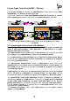
The second Light-Display-Module has been connected to the first Module via a Patch-Cable.