
User manual


Layout-Light-Control Light-DEC – Manual
- 5 -
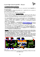
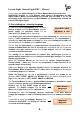
It is as well possible to connect the Light-Modules to each other via the “Kabel
Light@Night” at a distance of 0.5m, 1m or 2m.
On this way can be as well older Light-Modules without RJ-45 sockets for a patch-
cable connection connected to each other on a longer distance of up to 2m.
BU1
GBS-Display / Light-Display
Rev. 1.8
braun
Littfinski DatenTechnik (LDT)
gelb
10...18V~
12...24V=
KL6
KL7
1
2
3
4
5
6
7
8
26
27
28
29
30
31
32
39
38
37
36
35
34
33
25
9
10
11
12
13
14
15
16
18
19
20
21
22
23
24
17
40
ST1
KL4 KL3 KL2 KL1
KL5
white
weiss
white
weiss
BU2
BU3
OUT
IN
BU1
GBS-Display / Light-Display
Rev. 1.8
braun
Littfinski DatenTechnik (LDT)
gelb
10...18V~
12...24V=
KL6
KL7
1
2
3
4
5
6
7
8
26
27
28
29
30
31
32
39
38
37
36
35
34
33
25
9
10
11
12
13
14
15
16
18
19
20
21
22
23
24
17
40
ST1
KL4 KL3 KL2 KL1
KL5
white
weiss
white
weiss
BU2
BU3
OUT
IN
weiss
white
xm
weiss
white
Stiftleiste (Adapter)
pin plug (adapter)
Bestellbezeichnung /
Order code: Kabel Light@Night xm
BU1
Littfinski DatenTechnik (LDT)
Light-DEC-Basis
Rev. 1.0
Taster / Button
KL1 KL2 KL3 KL4
+5V
GND
1
2
3
4
5
6
7
8
IC5
D1
red brown
KL5
K J
Light-DEC-Service
Rev. 1.0
Littfinski DatenTechnik (LDT)
S1
S2
S4
S3
R1
Light-DEC V1.0
12:15:00 T 300
J
braun
brown
K
rot
red
Optional:
Von DCC-Digitalzentrale
oder Booster
From DCC command station
or booster
page_1606
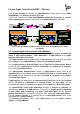
The second Light-Display-Module has been connected to the first Module via a Kabel
Light@Night.
2.2. Connect light sources to the Light-Modules
Some light-functions require only one light source (model railway incandescent
lamps or light emitting diodes – LED). Maximum is 10 light sources for the light-
function traffic-light cross-road.
If one light-function requires more than one light-source those have to be connected
to the clamps of the Light-Modules in series and ascending sequence.
For the light-function of Running Light 4 and 5, Fun-Fair and Construction Work 5
and 8 shall be the light-sources in series connected to the clamps at the sequence
of the actual installed situation.
The light-function Control-Center requires 3 light-sources, which have to be
implemented into the control center to simulate the light of a switch panel. The
first clamp shall be connected to the red, the second to the green and the third to
the yellow light-source.
3 light-sources are required for the light-function TV-Set which have to be installed
into the TV-room for simulation of a running TV-Set. The first clamp shall be
connected to the red, the second to the green and the third to the blue light-source.
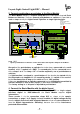
The light-function Traffic-Light Pedestrian occupies 5 clamps but provides via
those clamps voltage to 10 light-sources. There shall be 2 light-sources connected
to one clamp. Both Pedestrian- and both Traffic-road lights will be electrical
parallel switched on this way because they will show always the same light phases.
For the correct function is it required that the traffic-light-sources have to be
connected to the correct clamps.
The following illustration shows, which light-source has to be wired to which
clamp of the Light-Module.