
User manual
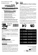


Littfinski DatenTechnik (LDT)
s88-N
Feedback Module
with integrated
8-fold track occupancy detector
for the s88-feedback bus
from the Digital-Professional-Series !
RM-GB-8-N-B Part-No.: 320101
>> kit <<
⇒ controls up to 8 different tracks
(current detection from 0,001[1mA] up to 3 ampere).
⇒ integrated voltage control
(avoiding “track free” feedback in case of power failures).
⇒ separated by opto isolation
(between track voltage and feedback bus).
⇒ s88 standard connections and s88N
(with 6-poles s88-pinbars and RJ-45 sockets].
⇒ suitable for following digital control systems:
Märklin Digital~/=, Central Station 1 and 2, Intellibox, TWIN-
CENTER, HSI-88 (-USB), EasyControl, ECoS, DiCoStation.
This product is not a toy! Not suitable for children under 14 years of age! The kit
contains small parts, which should be kept away from children under 3! Improper
use will imply danger of injuring due to sharp edges and tips! Please store this
instruction carefully.
CE Part-No.:
1370369
Introduction:
You have purchased the 8-fold feedback module RM-GB-8-N
with integrated detection of track occupancy for your model
railway. The RM-GB-8-N is a high quality product that is
supplied within the assortment of Littfinski DatenTechnik
(LDT).
We are wishing you having a good time using this product.
Feedback modules RM-GB-8-N of the Digital-Professional-
Series can be operated with your digital model railway without
any problems.
The RM-GB-8-N is suitable for all digital model railways with
s88 feedback bus.
General:
Tools required for the assembly
Please assure that the following tools are available:
• a small side cutter
• a mini soldering iron with a small tip
• solder tin (if possible 0,5mm diameter)
Safety Instructions
• All electrical and electronic components included in this kit
shall be used on low voltage only by using a tested and
approved voltage transducer (transformer). All components
are sensitive to heat. During soldering the heat shall be
applied for a very short period only.
• The soldering iron develops up to 400°C. Please keep
continual attention to this tool. Keep sufficient distance to
combustible material. Use a heat resistant pad for this work.
• This kit consist of small parts, which can be possibly
swallowed from children. Children (especially under 3 years)
shall not participate on the assembly without supervision.
Set-Up:
For the board assembly please follow exact the sequence of
the below assembly list. Cross each line off as done after
completing the insertion and the soldering of the respective
part.
For the diodes please keep special attention to the correct
polarity (marked line for the cathode).
With reason to different makes of electrolytic capacitor you
will find different markings of the polarity. Some are marked
with "+" and some are marked with "-". Each capacitor has to
be assembled to the board that the marking on the capacitor is
in correspondence with the marking on the pc-board.
Integrated circuits (IC`s) are either marked with a half round
notch on one end or a printed point for the correct mounting
position. Push the IC`s into the correct socket assuring that the
notch or the printed point is corresponding to the half-rounded
marking on the pc-board.
Please attend to the sensitivity of the ICs to electrostatic
discharge, which will cause immediate damage of the IC.
Before touching those components please discharge yourself
by contacting an earthed metal (e.g. radiator) or work with an
electrostatic safety pad.
Before assembling the clamps please connect the 2-pole and
the 3-pole clamps together to a block with 14 connections.
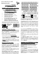
Please glue the below two label onto the RJ-45 sockets for the
identification of the output socket BU1 (wire directed to the
central unit) and BU2 (wire from the next feedback unit).
s88-N
OUT
IN
s88-N
Label for BU1 Label for BU2
Assembly List:
Made in Europe by
Littfinski DatenTechnik (LDT)
Kleiner Ring 9
D-25492 Heist/Germany
Phone: 0049 4122 / 977 381
Fax: 0049 4122 / 977 382
Internet: http://www.ldt-infocenter.com
Subject to technical changes and errors. 07/2015 by LDT
Märklin and Arnold are registered Trademarks.
Assembly Instruction
Pos.
Qty.
Component
Note
Ref.
Done
1 1 Printed Circuit Board
2 8 Resistors 39Ohm orange-white-black-gold R1..R8
3 1 Resistor 1MOhm brown-black-black-yellow R9
4 2 Resistors 4,7kOhm yellow-violet-black-brown R10, R17
5 4 Resistors 22kOhm red-red-black-red R11..14
6 1 Resistor 82kOhm gray-red-black-red R15
7 1 Resistor 100kOhm brown-black-black-orange R16
8 1 IC-Socket 18poles IC1
9 4 IC-Sockets 16poles IC2,3,5,6
10 1 IC-Socket 8poles IC4
11 3 Capacitors 100nF 100nF = 104 C1..C3
12 1 Resonator 2MHz CR1
13 1 Electrolytic-cap. 22uF/25V attend to the polarity! C4
14 2 6 Pin contact bar header ST1, ST2
15 32 Diodes BY251 attend to the polarity! D1..D32
16 6 Clamps 3poles form blocks before assembly KL1..6
17 1 Clamp 2poles form blocks before assembly KL7
18 2 RJ45 Sockets BU1, BU2
19 1 IC: Z86E0412PSC attend to the polarity! IC1
20 1 IC: 4052 attend to the polarity! IC2
21 1 IC: 4014 attend to the polarity! IC3
22 1 IC:LTV824 attend to the polarity! IC4
23 2 IC:LTV844 attend to the polarity! IC5, 6
End Control