
User's Manual


Installation & Basic Operation: RadioPopper JrX Receiver
1) Remove the battery compartment door on the top side of the unit. Insert a single CR123 Lithium battery. Take care
to follow the direction / polarity indications printed inside the battery clip. Secure the battery by pressing it straight
down into the clip - it will click into place. Replace the battery compartment door.
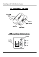
2) Connect the JrX Receiver to your lighting equipment - a studio strobe unit, power pack, mono light, or battery
powered strobe unit. Connect the appropriate cable between the Sync Port on the side of the JrX Receiver to the
trigger port or hot shoe connector of your lighting equipment. The cable that inserts into the JrX Receiver is a male
1/8” mini-phono plug. The sync port accepts mono or stereo type connectors. If you are using White Lightning,
Alien Bees, or Zeus brand studio lights, you may optionally attach the light via the RJ-11 / Telephone style Data Port
connector provided on the JrX Receiver. NOTE: The Data Port connector is only enabled in the “Studio” version of the JrX
Receiver. This port is NOT enabled in the “Basic” version of the JrX Receiver. For more information about the use of the
Data Port to control compatible studio lights, please refer to the section on page 12.
IMPORTANT NOTE: If using the Data Port Connector, it is NOT necessary to connect an additional cable to the Sync Port
to achieve activation of the attached light. However, some lights provide an optical slave triggering function where
they will activate when observing light from other sources. When using a light with an optical slave, connected by
the Data Port connector, and being used in conjunction with PX units include ETTL or iTTL type communications, it is
important to disable the optical triggering function by placing a plug or connector in the sync port of the light itself.
3) To power on the JrX Receiver, press and hold the power button for approximately two seconds. The Power LED will
light to indicate the unit is powered on and operational. The JrX Receiver will perform a self-test and will activate
the attached light a couple times. If a JrX Receiver “Studio” unit is attached to compatible lighting via the Data Port,
you will see the modeling lamp of that light cycle up and down during this self test. The self test is complete in
approximately ve seconds at which time the unit begins normal operation.
4) Congure the radio channel, group setting, and other settings using the Option Switches. Please refer to page 12
for details as to the settings of these switches.
5) Tap the Power button one time to cause the attached light to emit a test re.
6) To power o the unit, press and hole the Power button for approximately two seconds until the Power LED goes
dark.
Installation
Page 11