
User's Manual


Introduction
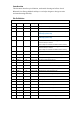
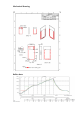
This document describes pin definition, mechanical drawing and reflow data of
Bluetooth Low Energy Module and hope it can helps designer to design in easier
and manufacturing smoothly.
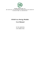
Pin Definition
Pin #
Pin Name
Direction
Voltage
Desription
1
VDD
I
1.8 to 3.3V
Input power can range from 1.8V to 3.3V
2
VSS
I
GND
Ground
3
TEST0
I/O
1.8V to 3.3V
Mfg Test pin 0;
MODE "POINTER". Internally
pulled-up (active low)
4
TEST1
I/O
1.8V to 3.3V
Mfg Test pin 1;
MODE "JOYSTICK". Internally
pulled-up (active low)
5
SDA
I/O
1.
8V
to
3.3V
I2C
data
to
interface
with
sensors
(gyro
&
accelerometer) for relative
motion. May also interface to additional I2C memory.
6
SCL
O
1.8V
to
3.3V
I2C
clock
to
interface
with
sensors
(gyro
&
accelerometer) for relative
motion. May also interface to additional I2C memory.
7
TEST2
I/O
1.8V to 3.3V
Mfg Test pin 2
8
GPIO_2
I/O
1.8V to 3.3V
Interrupt from I2C accelerometer. Internally pulled-up.
9
GPIO_3
I/O
1.8V to 3.3V
Interrupt from I2C gyro. Internally pulled-up.
10
GPIO_0
I/O
1.8V to 3.3V
"A" button. Internally pulled-up.
11
GPIO_1
I/O
1.8V to 3.3V
"B" button. Internally pulled-up.
12
GPIO_4
I/O
1.8V to 3.3V
General I/O
-
UNUSED. Internally pulled
-
up.
13
GPIO_5
I/O
1.8V to 3.3V
"HOME" button. Internally pulled-up.
14
GPIO_6
I/O
1.8V to 3.3V
"HELP" button. Internally pulled-up.
15
GPIO_7
I/O
1.8V to 3.3V
"PAUSE"
button.
Internally
pulled
-
up.
16
GPIO_10
I/O
1.8V to 3.3V
LED
for
player
"1".
17
GPIO_11
I/O
1.8V to 3.3V
LED
for
player
"2".
18
ADC_0
I
1.8V to 3.3V
ADC input for X direction on joystick.
19
ADC_1
I
1.8V to 3.3V
ADC input for Y direction on joystick.
20
ADC_2
I
1.8V to 3.3V
ADC input for battery voltage.
21
GPIO_8
I/O
1.8V to 3.3V
Power LED.
22
GPIO_9
I/O
1.8V to 3.3V
IR LED.
23
GPIO_12
I/O
1.8V to 3.3V
General
I/O
-
UNUSED.
Internally
pulled
-
up.