
Information


Teledyne LeCroy WaveAce Integration with LogicStudio page | 10 of 10
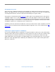
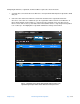
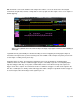
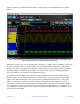
Finally, LogicStudio is equally adept with the display of analog signals as it is with digital signals as shown in
Figure 11.
Figure 11: This LogicStudio screen capture demonstrates the software’s ability to display a mixture of analog signals, digital
signals, and serial protocols as captured on the WaveAce oscilloscope.
Displaying of signals such as the sine and ramp waves in Figure 11 is simply a matter of applying the same setup
procedures described earlier to the analog signals. In the channel configuration for Channels 1 and 2 from the
WaveAce, the signals are designated in LogicStudio as analog channels. Note that when a channel is given the
type “Analog Signal,” the digital I/O pin designations are greyed out in the channel configuration dialog box.
Instead, the Channels 1-4 designations from the WaveAce are live.
It’s important to note that digital signals acquired using the LogicStudio module and analog signals from the
WaveAce oscilloscope are displayed aligned in time on the PC. Thus, users may capture analog and digital
signals on two different instruments and accurately measure the digital signals with reference to the analog
signals. For example, it is possible to measure the delay in capacitor discharge time (analog) after an I
2
C
command is issued by a microcontroller (digital). LogicStudio software comes with a full complement of timing
cursors that make it easy to measure the time between transitions on a single digital line, across digital lines, or
from a digital line to an analog waveform. As a result, users gain mixed-signal oscilloscope capabilities at a cost
far lower than an actual MSO.